Methods for fabricating lenses at the end of optical fibers in the far field of the fiber aperture

a technology of optical fiber and fiber aperture, which is applied in the field of microlenses fabrication, can solve the problems of expensive commercial scale production of lenses and focus beams, and achieve the effects of low shrinkage, good thermal stability, and high transparency

Inactive Publication Date: 2006-10-31
UNIV OF SOUTH FLORIDA
View PDF19 Cites 15 Cited by
  • Summary
  • Abstract
  • Description
  • Claims
  • Application Information

AI Technical Summary

Benefits of technology

[0011]The long-standing but heretofore unfulfilled need for a method for fabricating lenses at the end of optical fibers in the far field of the fiber aperture is now met by a new, useful, and nonobvious method that includes the steps of selecting a lens material from a group of lens materials having a large refractive index, high transparency, low shrinkage upon curing, good thermal stability, and ease of curing while centrifuged. A droplet of said lens material is applied to a preselected end of the optical fiber, followed by application of a predetermined artificial gravitational acceleration by spinning the optical fiber and droplet in a centrifuge. The lens material is cured by a suitable means as the optical fiber is spinning.

Problems solved by technology

However such a lens, at best, can only focus the output beam.
Moreover, such lenses would be expensive to produce on a commercial scale.

Method used


Image

  • Methods for fabricating lenses at the end of optical fibers in the far field of the fiber aperture
  • Methods for fabricating lenses at the end of optical fibers in the far field of the fiber aperture
  • Methods for fabricating lenses at the end of optical fibers in the far field of the fiber aperture

Examples


first embodiment

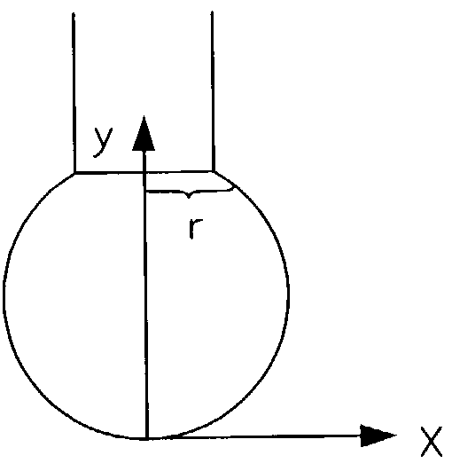
[0052]In a first embodiment, the lens material is a droplet of photopolymer, thermoplastic, sol-gel, or the like and is applied to a preselected end of a rod or fiber. The lens material is selected from the group of suitable lens materials having a large refractive index, high transparency, low shrinkage upon curing, good thermal stability, and ease of curing while centrifuged. The optical fiber is cleaved at a preselected end and the coating of optical fiber is removed with a stripping agent. The droplet is applied at the cleaved end and the optical fiber and droplet are placed in an artificial gravitational acceleration.

[0053]The shape of the liquid drop is found from Laplace's formula:

[0054]1R1+1R2+g⁢⁢ρ⁢⁢yα=const.(equation⁢⁢1)

[0055]where R1 and R2 are the principal radii of curvature, g is gravitational acceleration, ρ is the density of the liquid, and α is the surface tension coefficient for the liquid. When the capillary constant

[0056]a=2⁢ag⁢⁢ρ

is much larger than the dimensions...

second embodiment

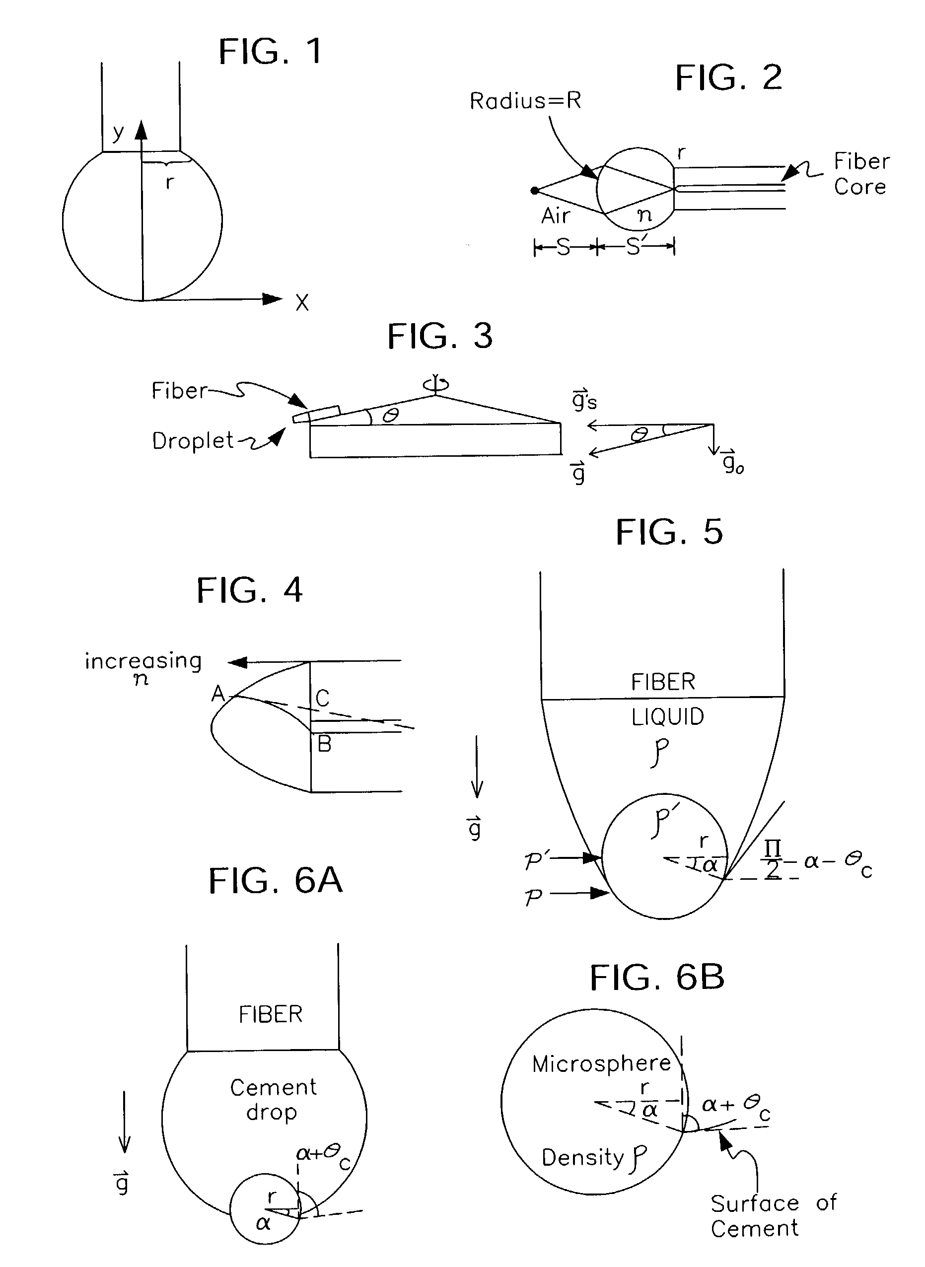
[0070]In the invention, the refractive index of the polymer or sol-gel is increased by mixing in high refractive index nanoparticles formed of a transparent material such as Ti2O3. This also enables producing a microlens with a graded refractive index along the optical axis through centrifugation as depicted in FIG. 4.

[0071]Solid line AB indicates a bent ray as a result of the graded index, and dashed line AC is a straight line the ray would follow without the gradient.

Positioning of Microsphere at End of Optical Fiber by Artificial Gravity

third embodiment

[0072]In a third embodiment, a microsphere is attached to the end of an optical fiber by using an optical cement for the purpose of focusing the light coming out of the fiber. The focusing properties of the microsphere depend on the thickness of the cement in between. The novel technique of this invention allows the controlled positioning of the microsphere by applying an artificial gravitational acceleration to the fiber / microsphere assembly before the cement is cured.

[0073]When a fiber tipped with a liquid containing a microsphere is held vertically with the droplet hanging at the bottom, the microsphere protrudes out of the liquid if it has a density greater than that of the liquid, as depicted in FIG. 5. The extent of protrusion depends upon its size and its surface interaction with the liquid, the radius of the fiber, the surface tension of the liquid, etc.

[0074]By balancing the “weight” of the microsphere with the buoyant force of the liquid and the atmosphere outside, to have...


PUM

PropertyMeasurementUnit
contact angleaaaaaaaaaa
diametersaaaaaaaaaa
gravitational accelerationaaaaaaaaaa

Abstract

A microlens is affixed in the far field of an optical fiber to spatially transform a beam either entering or exiting the fiber. In a first embodiment, a droplet of photo polymer is placed on the end of an optical fiber and the fiber is spun to create an artificial gravity. The droplet is cured by UV radiation during the spinning. In a second embodiment, nanoparticles are mixed into the droplet to increase the refractive index of the photo polymer. A third embodiment employs artificial gravity to attach a microsphere to the end of the optical fiber. A fourth embodiment chemically treats the surface of the microsphere so that the requirement of artificial gravity is either reduced or eliminated. In a fifth embodiment the droplet is cured under equlibrium or nonequilibrium conditions to obtain different final shapes for the lenslet. A sixth embodiment discloses fabrication of microlens arrays.

Description

CROSS REFERENCE TO RELATED APPLICATION[0001]This disclosure is a continuation-in-part of a co-pending disclosure of the same title by the same inventor, filed Feb. 20, 2002, bearing Ser. No. 60 / 358,143.BACKGROUND OF THE INVENTION[0002]1. Field of the Invention[0003]This invention relates, generally, to the fabrication of microlenses attached to the end of optical fibers or small cylindrical rods in general. The purpose of the microlens is to focus light entering or leaving the fiber or mini-rod.[0004]2. Description of the Prior Art[0005]Lenses are used in fiber optics for coupling a signal propagating through an optical fiber into preselected photonic components. An optical beam exiting a fiber must be focused or collimated to facilitate its coupling to a preselected photonic component.[0006]External lenses, one of which is known as the GRIN lens, are in current use.[0007]Attempts, with varying degrees of success, have been made to improve upon such external lenses by positioning a ...

Claims


Application Information

Patent Timeline
Patent Type & Authority Patents(United States)
IPC IPC(8): B05D5/06
CPCG02B3/00G02B3/0012G02B6/262G02B6/32Y10S425/129
Inventor DJEU, NICHOLAS
Owner UNIV OF SOUTH FLORIDA
Why Eureka
Try Eureka