Roll printer with decomposed raster scan and X-Y distortion correction

a raster scan and raster scanner technology, applied in the field of semiconductor circuits and display panels, can solve the problems of insufficient correction of achromatic systems (corrected for two wavelengths), insensitive to the color of broadband sources, bulky and expensive apochromatic systems (three or more wavelengths) and insufficient correction of achromatic systems (corrected for two wavelengths). , to achieve the effect of a considerable variation in the level of the format plan

Inactive Publication Date: 2006-10-31
WHITNEY THEODORE R
View PDF33 Cites 2 Cited by
  • Summary
  • Abstract
  • Description
  • Claims
  • Application Information

AI Technical Summary

Benefits of technology

[0015]The invention comprises a new machine layout, including an optical transfer assembly which shuttles reciprocally with respect to an intermittently stationary photomask and format assembly to provide in combination a raster scan, also providing slightly adjustable magnification, a reciprocally moving illumination system, and a photomask articulated within its frame to introduce slight relative motions in two dimensions. This combination of elements involving the moving optical system and the intermittently stationary photomask and format solves the notable problems of previous designs in a simple manner. There is plenty of room to use a large reflective achromatic optical system and still scan a large format, the two-dimensional effects of distortion are removed, the introduction of yaw angle error is avoided, and the web is fed through the machine without twisting or stress. It is designed to produces high-resolution images (better than 2 micron least dimension) everywhere on the format and layer to layer overlay accuracy in the micron region. The optics are completely achromatic and the system is therefore insensitive to the wavelength composition of the light which is supplied by the illuminator.
[0019]Autofocus is maintained by two proximity sensor gages and two servoed lifters, one under the object field and one under the image field. Optionally the photomask is carried in a vacuum support frame that helps to maintain the image surface flat, countering sag due to gravity. However, since focus is performed independently in each field, and corrected independently in each field, the object end of the apparatus can ride over a considerable residual curvature in the photomask without image degradation or change in magnification. For a similar reason, the image end of the optical train can also tolerate considerable variation in the level of the format plane.

Problems solved by technology

Such images contain from 2–500,000 resolved points across in one dimension, and are thus far out of reach of a stationary camera lens, however complex, which resolves—at a maximum—something like 50,000 points in each direction.
Achromatic systems (corrected for two wavelengths) are not sufficiently well corrected.
Apochromatic systems (three or more wavelengths) are bulky and expensive.
Mirror systems, however, are corrected for all wavelengths, and hence insensitive to the color of the broadband source.
It is inherently more difficult mechanically to introduce two orthogonal motions into a single moving assembly than it is to split the two motions, introducing the cross-scan by the motion of one assembly and the intermittent motion, between scans, into the orthogonal member.
Flexible plastic substrates are much more dimensionally unstable, in that they are sensitive to humidity as well as to heat and process variables.
When a large photomask and a large web are laid side by side and incorporated mechanically into a single assembly, and if that assembly is moved back and forth and intermittently forward across the fields of a stationary optical system to produce the raster scanning pattern, then this scanning pattern requires that the web be twisted in ways which will tend to introduce a component of unwanted distortion.

Method used


Image

  • Roll printer with decomposed raster scan and X-Y distortion correction
  • Roll printer with decomposed raster scan and X-Y distortion correction
  • Roll printer with decomposed raster scan and X-Y distortion correction

Examples


Embodiment Construction

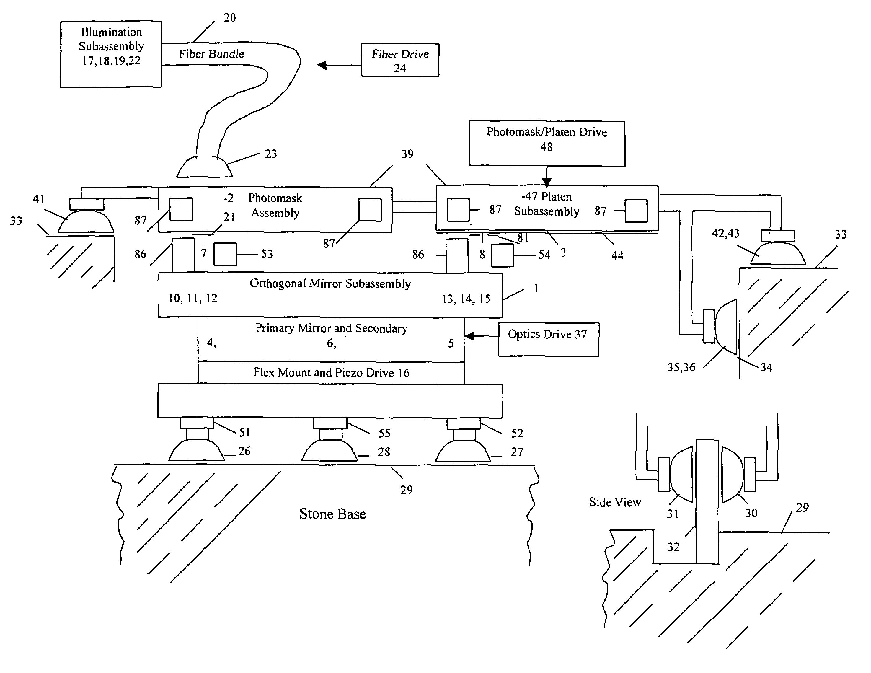
[0044]The preferred embodiment of this invention is an optical machine for the processing of display screens, multilayer circuits constructed on flexible material and the like. It comprises a series of assemblies which operate together under the control of a multiaxis controller, to produce large exposed patterns or panels in a semi-automatic manner. The separate assemblies will be described separately followed by a description of the way in which they work together.

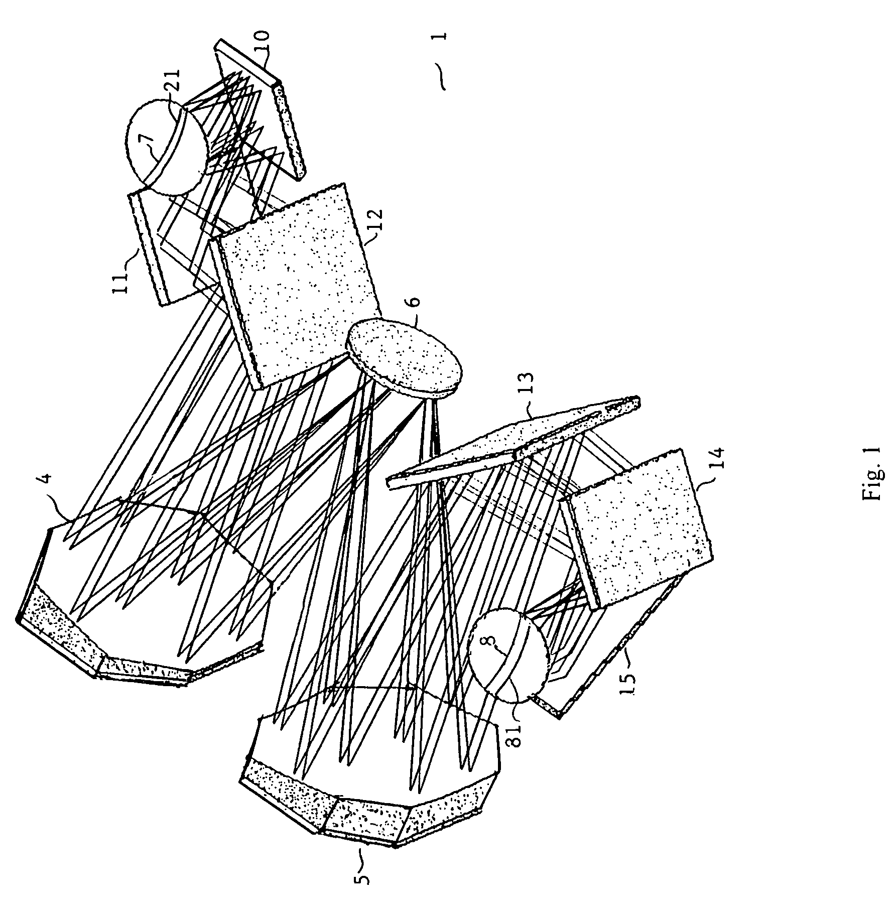
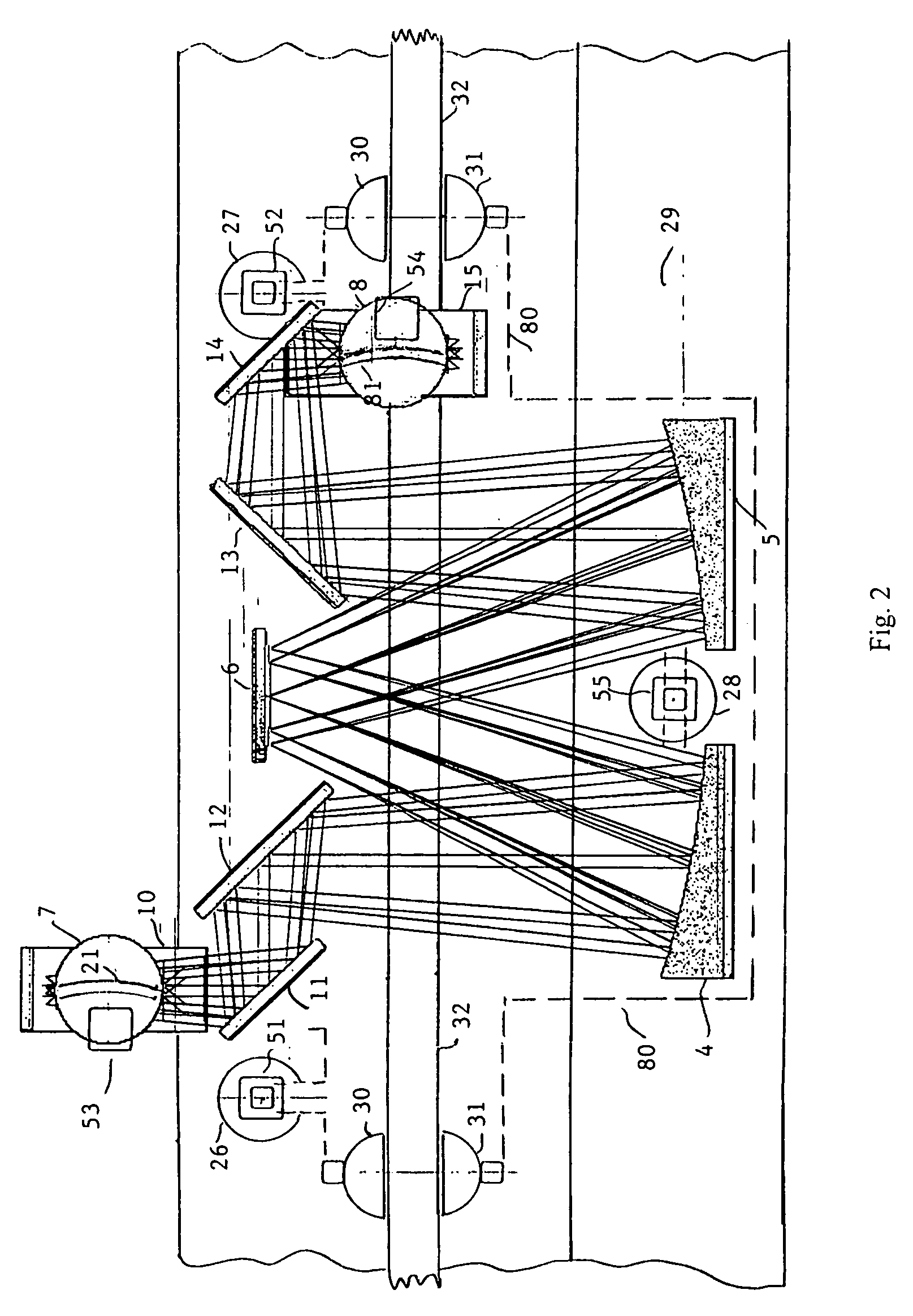
[0045]The optical transfer assembly 1, FIGS. 1–5, which images detail from the photomask 2 to the format 3 is an all-reflecting erecting configuration similar to the arrangement first described by Offner, Ref. 2 except that the primary concave mirror is composed of two controllably moveable smaller mirrors, the secondary mirror is aspheric, and the erecting mirrors are differently and more advantageously arranged. The two primary mirrors are concave spheres 4, 5 and one, the convex secondary, is aspheric, 6. FIG. 1 shows...


PUM

PropertyMeasurementUnit
sizesaaaaaaaaaa
sizesaaaaaaaaaa
sizesaaaaaaaaaa

Abstract

A photolithographic machine is described for transferring fine patterns from a photomask to a flexible roll-to-roll format. It is capable of printing multiple layers in exact registry onto a distorted format. It contains 1 to 1 reflective optics, dynamic distortion and magnification correction. The optical transfer assembly scans reciprocally across the format and back and the photomask / platen assembly moves incrementally forward between scans to complete a raster pattern. Both the object and image fields are autofocussed. The optical transfer assembly is retained into a straight-line scanning path by opposed air bearings retained on a straight guide. The photomask / platen assembly is retained into an orthogonal path by air / vacuum bearings operating on a vertical stone face. Together this arrangement substantially prevents yaw scanning errors. The web is fed through the machine from roll to roll without twisting. It remains stationary during each recording pass.

Description

REFERENCE TO PRIOR APPLICATION[0001]This application relies for priority on provisional application Ser. No. 60 / 467,110 filed Apr. 30, 2003, and entitled “Roll printer with decomposed raster scan and X-Y distortion correction”. A table of additional references, which are referred to in the specification, follows as Appendix 1.FIELD OF THE INVENTION[0002]This invention relates to the manufacture of semiconductor circuits, display panels, photochemically produced parts and the like on flexible material, and more specifically to a roll-to-roll machine which optically copies an object field onto an image field at unity magnification.PRIOR ART[0003]In semiconductor photolithography, in flat panel manufacture and in the manufacture of photochemically produced parts, the creation of images of very fine resolution and at the same time of very large area is of great importance. For example 1–2 micron image resolution is being demanded over fields or panel sizes as large as 24 inches, and 0.1...

Claims


Application Information

Patent Timeline
Patent Type & Authority Patents(United States)
IPC IPC(8): G03B27/44G03B27/42G03B27/52G03F7/20
CPCG03B27/42G03B27/44G03F7/70233G03F7/70791
Inventor WHITNEY, THEODORE R.
Owner WHITNEY THEODORE R
Why Eureka
Try Eureka