
High throughput multi-dimensional sample analysis

a multi-dimensional sample and sample technology, applied in the field of high-throughput multi-dimensional sample analysis, can solve the problems of difficult to identify or characterize individual components using only lc, unstable ions of increasing mass-to-charge ratio, and inability to integrate hplc/ms systems efficiently

Active Publication Date: 2006-11-07
AGILENT TECH INC
View PDF16 Cites 37 Cited by
  • Summary
  • Abstract
  • Description
  • Claims
  • Application Information

AI Technical Summary

Problems solved by technology

As a result, LC is well suited for quantitative analysis, but it is difficult to identify or characterize individual components using only LC, particularly when novel or previously uncharacterized compounds are used.
In ion trap instruments, ions of increasing mass-to-charge ratio successively become unstable as the radio frequency voltage is scanned.
There exist challenges, however, in providing efficient integrated HPLC / MS systems.
Conventional MS systems are capable of much faster sample analysis than HPLC systems, and are much more expensive by a factor of roughly four to five times the cost of a single-column HPLC system.
Integrated HPLC / MS systems including a single HPLC column coupled to a MS by way of an ESI interface are known, but they suffer from limited utility since the overall system throughput is limited by the HPLC column, which requires several minutes to separate a single sample.
In other words, a HPLC / MS system having only a single HPLC column fails to utilize the rapid analytical capabilities of the MS portion efficiently.
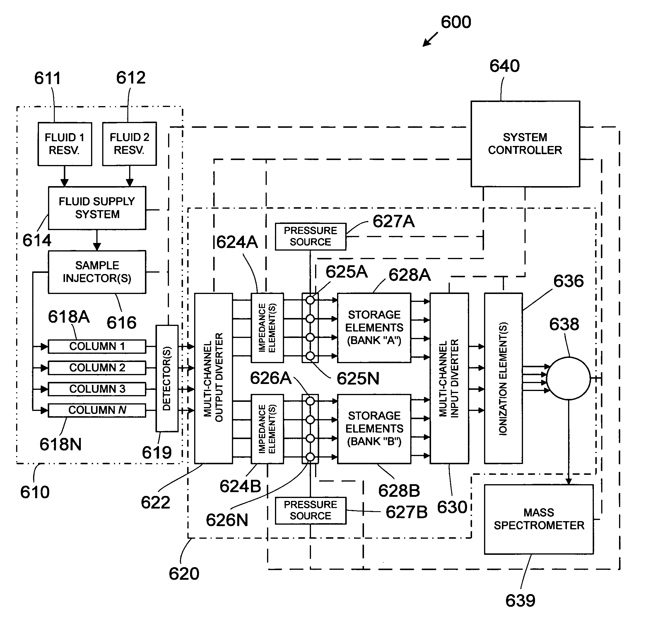
HPLC / MS systems having multiple HPLC columns coupled to a single MS are also known and provide greater separation efficiency compared to single-column HPLC / MS systems; however, conventionally-coupled multi-column HPLC / MS systems still suffer from limited utility.
While one stream is being analyzed, the others must continue to flow, as these systems have no storage capacity.
This inherently results in data loss.
The MS instrument thus receives very small plugs of sample, reducing the ability of the instrument to integrate data in order to eliminate noise and resulting in reduced signal clarity.
Such systems are extremely complex and expensive to operate and maintain.

Method used


Image

  • High throughput multi-dimensional sample analysis
  • High throughput multi-dimensional sample analysis
  • High throughput multi-dimensional sample analysis

Examples


Embodiment Construction

A. Definitions

[0040]The terms “column” or “separation column” as used herein are used interchangeably and refer to a region of a fluidic device that contains stationary phase material and is adapted to perform a separation process.

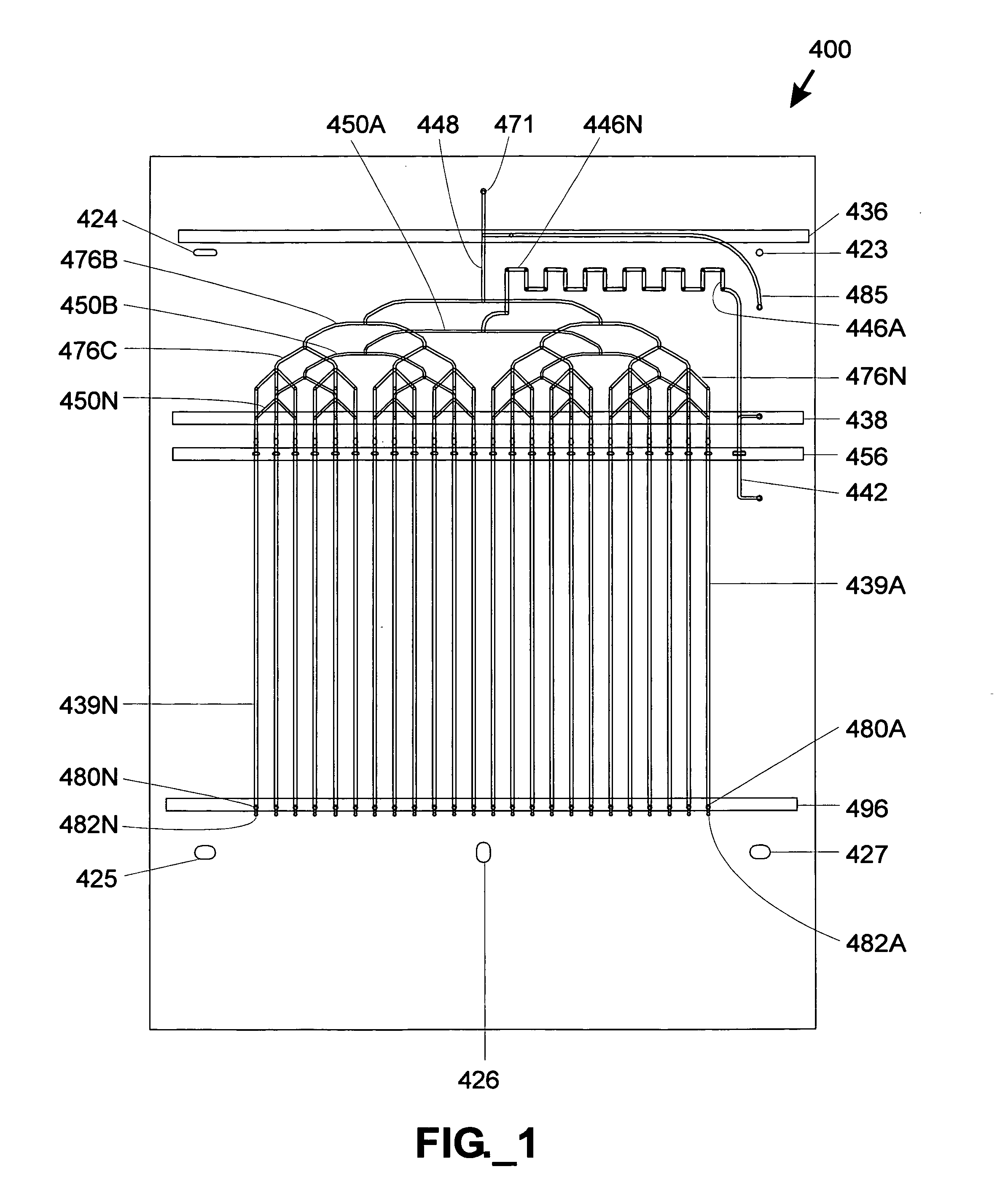
[0041]The term “fluidic distribution network” refers to an interconnected, branched group of channels and / or conduits capable of adapted to divide a fluid stream into multiple substreams.

[0042]The term “frit” refers to a liquid-permeable material adapted to retain stationary phase material within a separation column.

[0043]The term “liquid phase separation process region” as used herein refers to any region adapted to perform a liquid phase chemical or biochemical analytical process such as chromatographic, electrophoretic, electrochromatographic, immunoaffinity, gel filtration, and / or density gradient separation. A separation column is one type of a liquid phase separation process region.

[0044]The term “mass analyzer” as used herein refers to an analytical...


PUM


Abstract

High throughput analytical systems and methods employing multiple liquid phase separation process regions coupled to a common mass spectrometer are provided. Disclosed systems and methods permits parallel separation and parallel storage of discrete eluate fractions, followed by sequential discharge and ionization of previously stored eluate portions to yield a composite ion stream containing the sequential series of eluate portions, followed by mass analysis of the ion stream. A common manifold may receive ions and utilize pressurized gas or ion gating to direct ions within the manifold toward the mass spectrometer inlet.

Description

FIELD OF THE INVENTION[0001]The present invention relates to systems and methods employing multiple chromatographic separation columns coupled to a common mass spectrometer.BACKGROUND OF THE INVENTION[0002]Recent developments in the pharmaceutical industry and in combinatorial chemistry have exponentially increased the number of potentially useful compounds, each of which must be characterized in order to identify their active components and / or establish processes for their synthesis. To more quickly analyze these compounds, researchers have sought to automate analytical processes and to implement analytical processes in parallel.[0003]One useful analytical process is chromatography, which encompasses a number of methods that are used for separating ions or molecules that are dissolved in or otherwise mixed into a solvent. Liquid chromatography (“LC”) is a physical method of separation wherein a liquid “mobile phase” (typically consisting of one or more solvents) carries a sample co...

Claims


Application Information

Patent Timeline
IPC IPC(8): H01J49/42
CPCG01N30/7233G01N30/80H01J49/0018H01J49/0431H01J49/107G01N30/466Y10T436/115831G01N2030/8447Y10T137/86871Y10T137/86863
Inventor GAMBLE, RONALD C.O'CONNOR, STEPHEN D.WILCOX, BRUCEGREGORI, MATTHEW M.
Owner AGILENT TECH INC
Learn More