Control of electrolysis gases in electroosmotic pump systems

a pump system and electrolysis technology, applied in the direction of electrolysis, fluid speed measurement, liquid degasification by filtration, etc., can solve the problems of reducing the volume and surface area available for cooling devices, reducing the efficiency of heat sinks, and both heat pipes and vapor chambers are subject to the same basic physical limit, so as to minimize the spatial and temporal temperature variations of devices, minimize the shape and distribution of microchannels, and minimize the effect of device temperature variation

Inactive Publication Date: 2006-11-14
THE BOARD OF TRUSTEES OF THE LELAND STANFORD JUNIOR UNIV
View PDF177 Cites 53 Cited by
  • Summary
  • Abstract
  • Description
  • Claims
  • Application Information

AI Technical Summary

Benefits of technology

[0025]The present invention also optimizes the shape and distribution of microchannels in the micro heat exchanger and minimizes spatial and temporal temperature variations on the device, even considering large spatial and temporal changes in the heat flux due to variations in the operation of the device.
[0026]The present invention also has the capability of minimizing the temperature variations in the device, even in the presence of large nonuniformities in heat flux, which can have a strongly detrimental effect on its performance and reliability. This is achieved through the tailoring of placement, geometry, and internal features of the microchannel heat exchanger. Optimal microchannel design is achieved using simulation capability of the present invention.
[0027]The present invention provides flexibility in the location of the heat rejection elements, in particular enabling a large separation from the location of the heat generating device. Also enabled is a large area for rejection, which reduces the thermal resistance of the rejection and of the system as a whole.
[0028]Apparatus and methods according to the present invention preferably utilize electroosmotic pumps that are capable of generating high pressure and flow without moving mechanical parts and the associated generation of unacceptable electrical and acoustic noise, as well as the associated reduction in reliability. These electroosmotic pumps are preferably fabricated with materials and structures that improve performance, efficiency, and reduce weight and manufacturing cost relative to presently available micropumps. These electroosmotic pumps also preferably allow for control including venting or recapture of evolved gases and deposited materials, which may provide for long-term closed-loop operation. A gas permeable membrane removes and vents electrolytic gases generated within the fluid chamber of the electroosmotic pump to ambient. A catalyst can be used to recombine electrolytic gases to form a vapor product that can be vented or condensed into a liquid state. An osmotic membrane provides for re-entry of condensed fluid to the fluid chamber.
[0029]Apparatus and methods according to the present invention also allow active regulation of the temperature of the device through electrical control of the flow through the pump and can utilize multiple cooling loops to allow independent regulation of the special and temporal characteristics of the device temperature profiles.

Problems solved by technology

Conventional heat sinks are simply incapable of removing the targeted powers and power densities within a volume consistent with system design and market expectations.
This situation is exacerbated by targeted reductions of total system volume, which diminish the volume and surface area available for cooling devices.
The interaction of these two trends (increasing head load and decreasing system volume) are recognized as a critical problem for the future of the semiconductor industry, and for other industries that rely on heat-generating or absorbing devices.
Both heat pipes and vapor chambers are subject to the same basic physical limit for the peak power: The longer the separation between the heat source and the heat sink, and the smaller the cross sectional area, the smaller the total heat power that can be removed before these devices reach the capillary limit, or dry-out, condition.
In these applications, the heat from the device is transported to the rejection surface, and significant excess heat is added due to the limited thermodynamic efficiency of the cooling mechanism.
Cooling water is used in situations where large quantities of heat are generated, and the other methods described herein are unable to reject the heat to the surrounding air.
These pumps, to date, appear to be incapable of generating the pressure and / or flow necessary for application to removal of high heat flux from high-power devices.
These issues tend to be prominent in closed-loop fluidic cooling systems employing pumps.

Method used


Image

  • Control of electrolysis gases in electroosmotic pump systems
  • Control of electrolysis gases in electroosmotic pump systems
  • Control of electrolysis gases in electroosmotic pump systems

Examples


Embodiment Construction

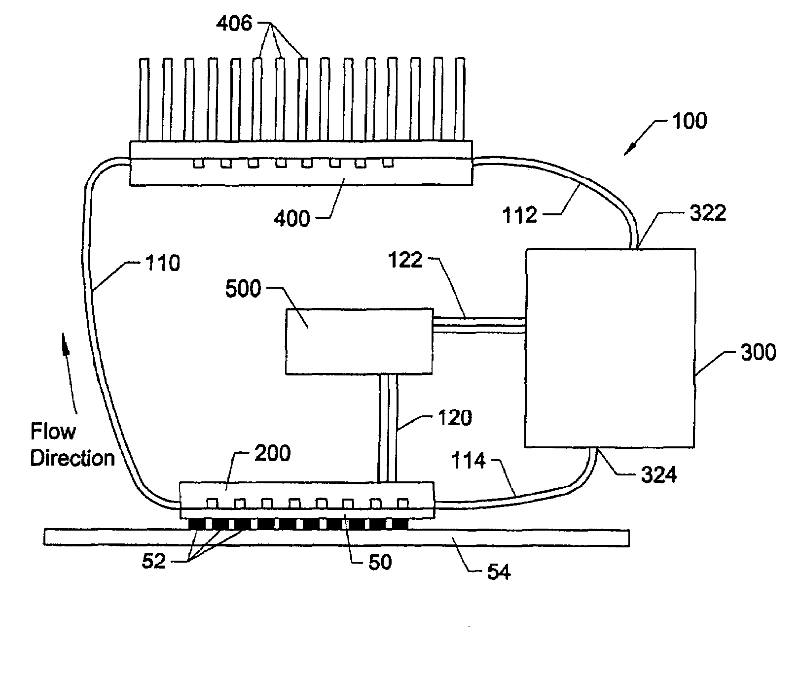
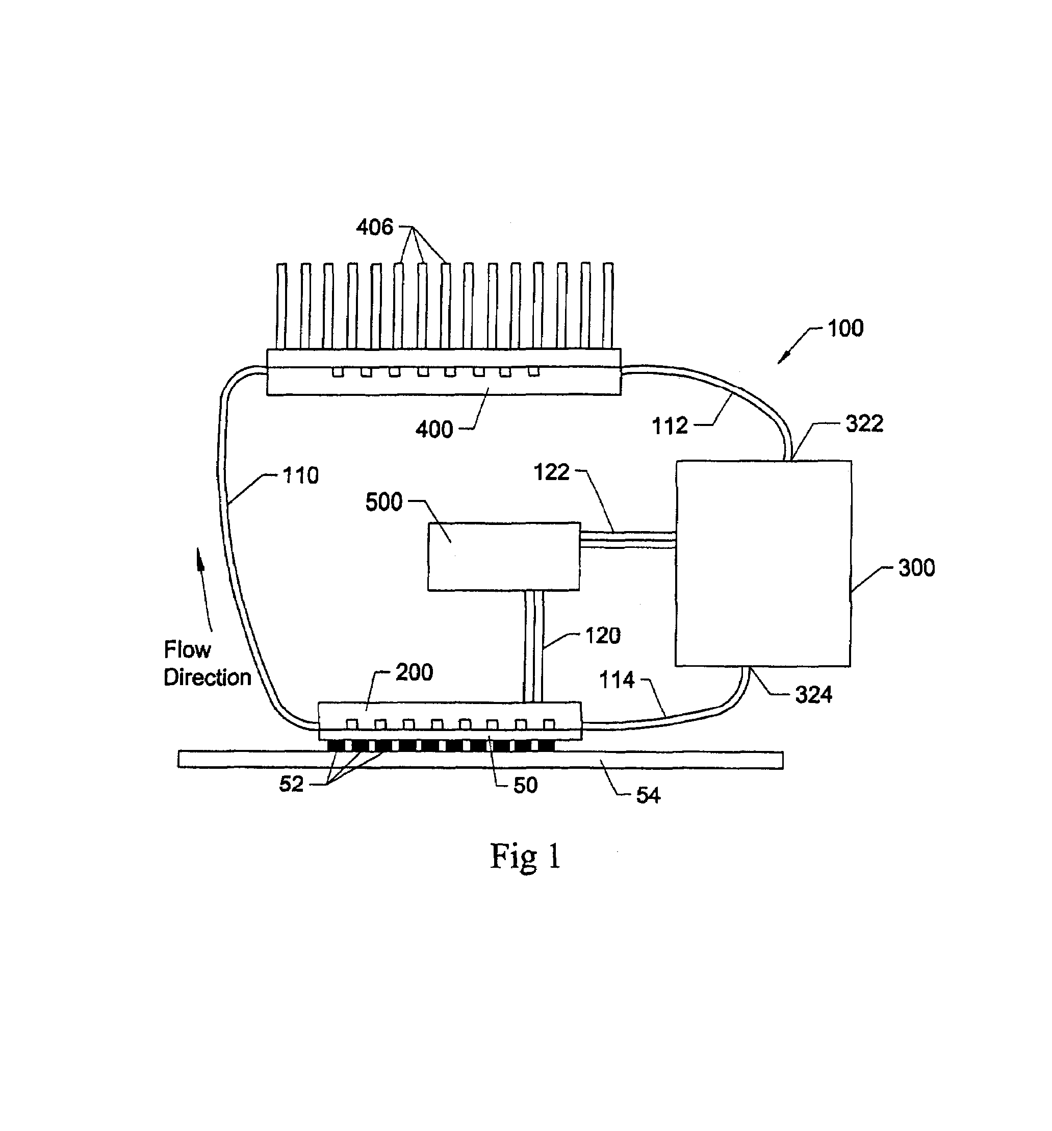
[0074]The present invention provides, in one aspect, a compact cooling system for electronic systems based on micro heat exchangers, specifically microchannels machined in silicon or metals, and compact electroosmotic pumps. The system is hermetically-closed and may be arranged in a modular fashion, enabling efficient heat removal from a device, and transport to a convenient macro heat exchanger. The micro heat exchangers and electroosmotic pumps as described are extremely compact and power-efficient, such that the total system is far smaller and lighter than heat pipes, vapor chambers, and fin-array heat sinks usually used for removing comparable power from miniature devices. The system is intercoinected by flexible tubing and therefore offers advantages in design flexibility. Certain embodiments of the system are generally referred to as the loop system since in its preferred form the various components establish a closed-loop through which the liquid that provides for thermal ene...


PUM

PropertyMeasurementUnit
flow ratesaaaaaaaaaa
thicknessaaaaaaaaaa
timeaaaaaaaaaa

Abstract

Apparatus and methods according to the present invention preferably utilize electroosmotic pumps that are capable of generating high pressure and flow without moving mechanical parts and the associated generation of unacceptable electrical and acoustic noise, as well as the associated reduction in reliability. These electroosmotic pumps are preferably fabricated with materials and structures that improve performance, efficiency, and reduce weight and manufacturing cost relative to presently available micropumps. These electroosmotic pumps also preferably allow for control including venting or recapture of evolved gases and deposited materials, which may provide for long-term closed-loop operation. A gas permeable membrane removes and vents electrolytic gasses generated within the fluid chamber of the electroosmotic pump to ambient. A catalyst can be used to recombine electrolytic gases to form a vapor product that can be vented or condensed into a liquid state. An osmotic membrane provides for re-entry of condensed fluid to the fluid chamber.

Description

CROSS REFERENCE TO RELATED APPLICATION[0001]This is a continuation-in-part of application Ser. No. 10 / 053,859, filed Jan. 19, 2002, now U.S. Pat. No. 6,942,018 which claims the benefit of U.S. Provisional Application No. 60 / 326,151 filed Sep. 28, 2001.[0002]The inventions described herein were supported in part by DARPA / Air Force Contract F33615-99-C-1442.FIELD OF THE INVENTION[0003]This invention relates generally to removal of heat from heat generating devices. Specifically, this invention relates to removal of heat from integrated circuits, opto-electronic devices, power electronics, bioanalytical devices and any devices that dissipate or absorb sufficient heat so as to require specific means for heat removal.BACKGROUND OF THE INVENTION[0004]Electronic systems, including, for example, laptop, hand-held and desktop computers as well as cell phones operate through the use of input electrical power. These have the characteristic that some of the input power is converted to heat, and...

Claims


Application Information

Patent Timeline
Patent Type & Authority Patents(United States)
IPC IPC(8): F28D15/00B81B1/00B01D19/00B01D61/42F04B19/00F04F99/00F25D1/02F25D9/00F28D15/04F28D15/06H01L23/473H05K7/20
CPCB01D19/0031B01D61/427B01D67/0062F04B19/006F28D15/00F28D15/043F28D15/06H01L23/473F28F2260/02H01L2224/16H01L2224/48091H01L2224/48145H01L2224/73253H01L2225/06562H01L2924/01078H01L2924/09701H01L2924/10158H01L2924/3011H01L2924/00014H01L24/48H01L2924/01019H01L2924/01066H01L2924/01322H01L2224/45169H01L2924/00H01L2924/10253H01L2224/73257H01L2924/00012
Inventor SANTIAGO, JUAN G.ZENG, SHULIN
Owner THE BOARD OF TRUSTEES OF THE LELAND STANFORD JUNIOR UNIV
Why Eureka
Try Eureka