
Techniques for recovering optical spectral features using a chirped optical field

a technology of optical field and target optical spectrum, applied in the field of optical signal processing, can solve the problems of limited performance in the dynamic range of photo-detectors and analog to digital converters, affecting the accuracy of optical spectral features, etc., to achieve the effect of high resolution and fast measurement of spectral features

Active Publication Date: 2006-12-05
MONTANA STATE UNIVERSITY
View PDF1 Cites 13 Cited by
  • Summary
  • Abstract
  • Description
  • Claims
  • Application Information

AI Technical Summary

Benefits of technology

This approach enables accurate recovery of spectral features with arbitrarily fast readout chirp rates, eliminating the need for prior knowledge of spectral features and improving measurement efficiency and resolution, while reducing distortions and enhancing applicability across various applications.

Problems solved by technology

While useful in many applications, the approach of readout with a high bandwidth, Fourier-transform-limited coherent brief optical pulse or series of optical pulses at the full bandwidth of processing can suffer, at present, from the limited performance in dynamic range of photo-detectors and analog to digital converters (ADCs, also called digitizers) that are needed to make a measurement of any instantaneous high bandwidth optical signal.
Existing high bandwidth detectors and ADCs have limited performance and higher cost as compared to lower bandwidth detectors and digitizers.
It has been observed that the detected signal received by the detectors is not a simple mapping in time of a target optical spectrum with which the probe signal interacts, but often includes spurious features.
The composite ringing of multiple spectral features leads to a complex distortion of the target optical spectrum when mapped into a temporal readout signal.
Duppen et. al. also observed the problem that using a fast chirp rate results in distortions, or asymmetrical ringing on the response in frequency chirped four wave mixing experiments (K. Duppen, F. de Haan, E. T. J. Nibbering, and D. A. Wiersma, “Chirped four-wave mixing”, Phys. Rev. A. 47, 5120(1993)).
While a slow chirp rate can reduce such distortions, the use of a slow chirp rate is not always desirable or applicable.
For example, a disadvantage of the slow chirp rate requirement is the need to know or accurately estimate the spectral resolution of the finest significant features in the spectrum of interest.

Method used


Image

  • Techniques for recovering optical spectral features using a chirped optical field
  • Techniques for recovering optical spectral features using a chirped optical field
  • Techniques for recovering optical spectral features using a chirped optical field

Examples


embodiment 100

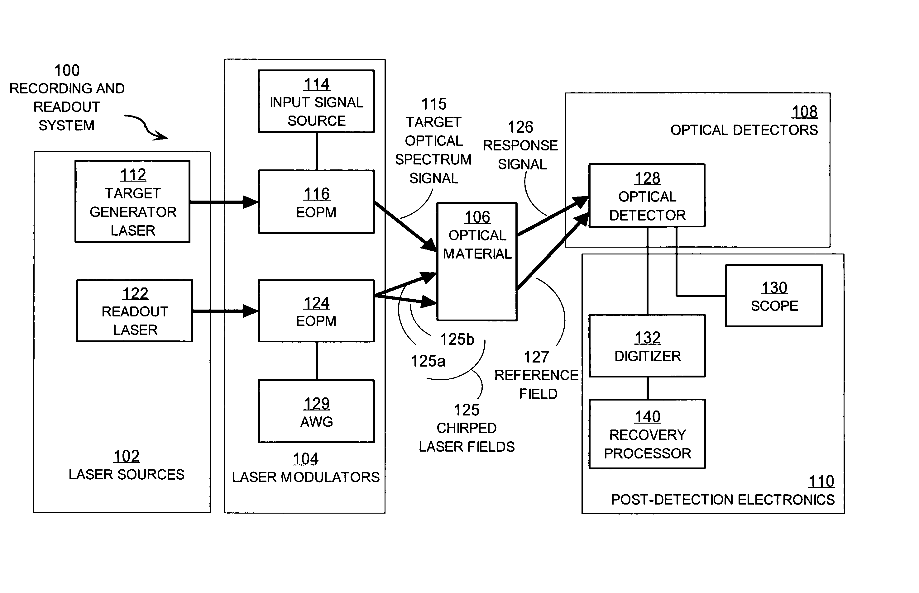
[0061]In the illustrated embodiment 100, laser sources 102 include an input laser 112 and a readout laser 122. These laser sources provided stabilized optical carrier frequency beams used to carry the target optical spectrum and the chirped laser field used as a probing waveform. In some embodiments, a single laser provides the carrier frequency beam for both the target optical spectrum and probe signals. In some embodiments, additional laser sources are included in laser sources 102.

[0062]The laser modulators 104 modulate the carrier frequency beams to produce signal beams with rich frequency content. In the illustrated embodiment, laser modulators 104 include input signal source 114, electro-optic phase modulators (EOPMs) 116, 124 and arbitrary waveform generator (AWG) 129. In some embodiments, one or more EOPMs 116, 124 are replaced with or added to other optical modulators such as one or more acousto-optic modulators (AOMs), electro-optic amplitude modulators, and electro-absorp...

embodiment 241

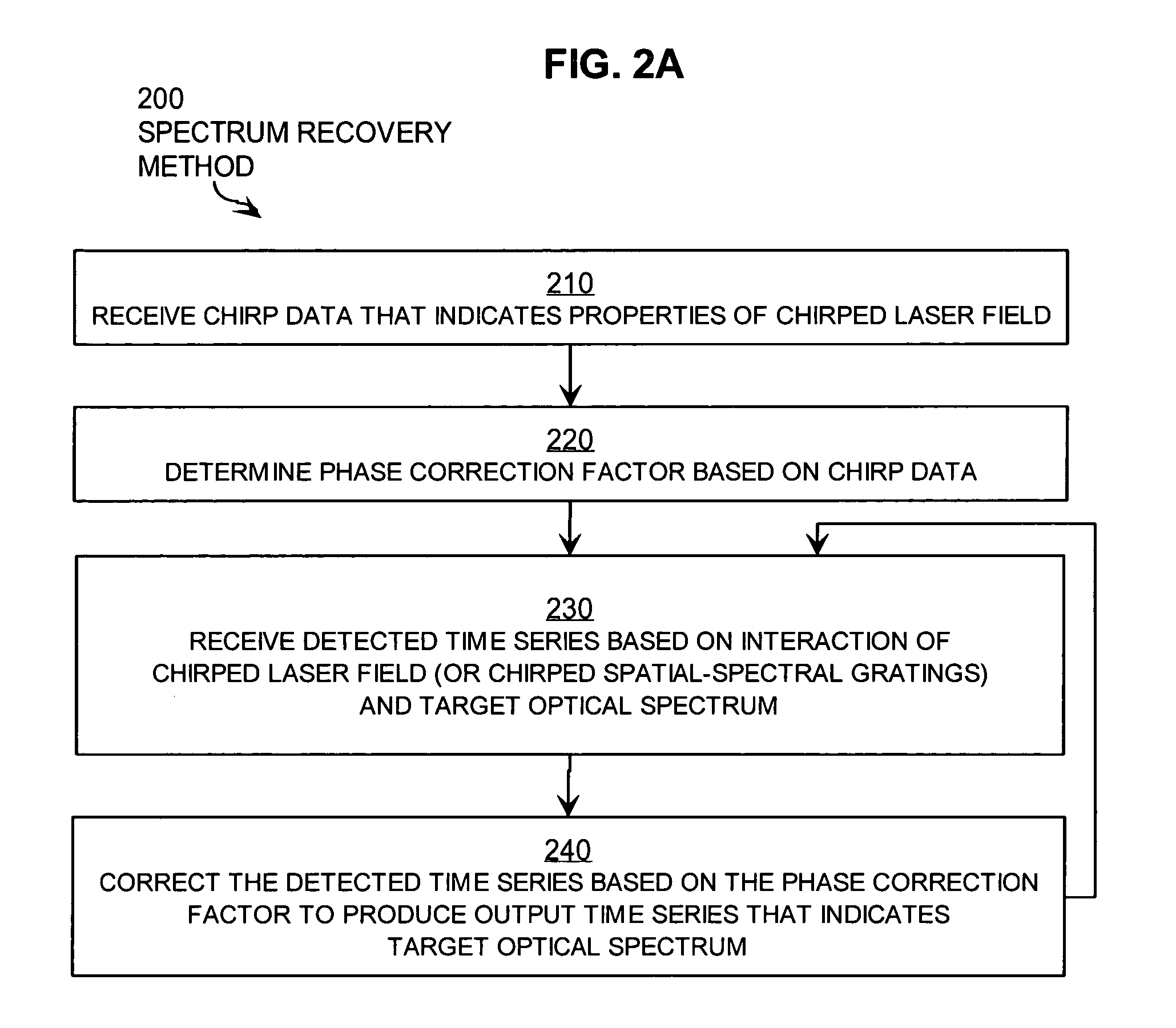
[0096]FIG. 2B is a flow diagram that illustrates in more detail a step of the method illustrated in FIG. 2A, according to an embodiment 241. Step 241 is a particular embodiment of step 240. Step 241 includes steps 252, 254, 256.

[0097]In step 252, the Fourier transform is determined for the detected time series. Any method may be used. There are efficient fast Fourier transform (FFT) software programs and microprocessor chips, which may be used in any combination to perform step 252.

[0098]In step 254, at each frequency, the spectral component in the Fourier transform is multiplied by the correction factor for the corresponding frequency as determined in step 220 to produce a corrected transform. For example, the amplitude of the Fourier transform of the detected series for frequency ν is multiplied by the value of C at frequency ν, as given by Expression 9a, above, to produce the amplitude and phase of the corrected transform at that frequency.

[0099]In step 256, the inverse Fourier t...

embodiment 201

[0100]FIG. 2C is a flow diagram that illustrates in more detail an embodiment 201 of the method illustrated in FIG. 2A. Method 201 is a particular embodiment of step 200, and includes an alternative to step 241. Method 201 implements the correction in the time domain using convolution, the mathematical equivalent of multiplication in the Fourier transform domain. The time domain data processing may be more computationally complex and may require different hardware than used in the Fourier transformed domain. Method 201 includes steps 210, 223, 230, 243. Steps 210 and 230 are as described above for method 200.

[0101]Step 223 is a particular embodiment of step 220, described above. Step 223 includes step 222. In step 222, the inverse Fourier transform of the correction factor is determined. Any method may be used to take the inverse Fourier transform of the correction factor, as described above for steps 252 and 256. There are efficient fast Fourier transform (FFT) software programs an...


PUM

PropertyMeasurementUnit
optical carrier frequencyaaaaaaaaaa
timeaaaaaaaaaa

Abstract

Techniques for recovering optical spectral features include receiving a detected time series that represents a temporally varying intensity of an optical signal. The optical signal is formed in response to an interaction between a target optical spectrum and a chirped optical field. The chirped optical field is an optical field that has a monochromatic frequency that varies in time. The target optical spectrum is an optical frequency dependent optical property of a material or device. A phase correction factor is determined based only on one or more properties of the chirped optical field. The detected time series is corrected based on the phase correction factor to produce an output time series that reproduces in time a shape of the target spectrum in frequency. These techniques allow for fast measurement of spectral features and eliminate the need for prior knowledge of the target optical spectrum to adjust the chirp rate.

Description

CROSS-REFERENCE TO RELATED APPLICATIONS[0001]This application claims benefit of Provisional Appln. 60 / 587,331, filed Jul. 13, 2004, the entire contents of which are hereby incorporated by reference as if fully set forth herein, under 35 U.S.C. §119(e).STATEMENT OF GOVERNMENTAL INTEREST[0002]This invention was made with Government support under Contract No. MDA-972-03-1-0002 awarded by the Defense Advanced Research Projects Agency and Montana Board of Research and Commercialization Technology (Grant #03-08). The Government has certain rights in the invention.BACKGROUND OF THE INVENTION[0003]1. Field of the Invention[0004]The present invention relates to optical signal processing to determine features of a target optical spectrum, and, in particular, to the use of a chirped optical field to recover the target optical spectrum. Here a target optical spectrum is a spectrum at optical frequencies that is output by a device, included inherently in a material or device, or recorded by arti...

Claims


Application Information

Patent Timeline
Patent Type & Authority Patents(United States)
IPC IPC(8): G02F2/00
CPCG01J3/02G01J3/0264G01J3/28G01J3/2889G01J3/4338G01J3/45
Inventor CHANG, TIEJUNTIAN, MINGZHENBABBITT, WILLIAM R.MERKEL, KRISTIAN
Owner MONTANA STATE UNIVERSITY
Learn More