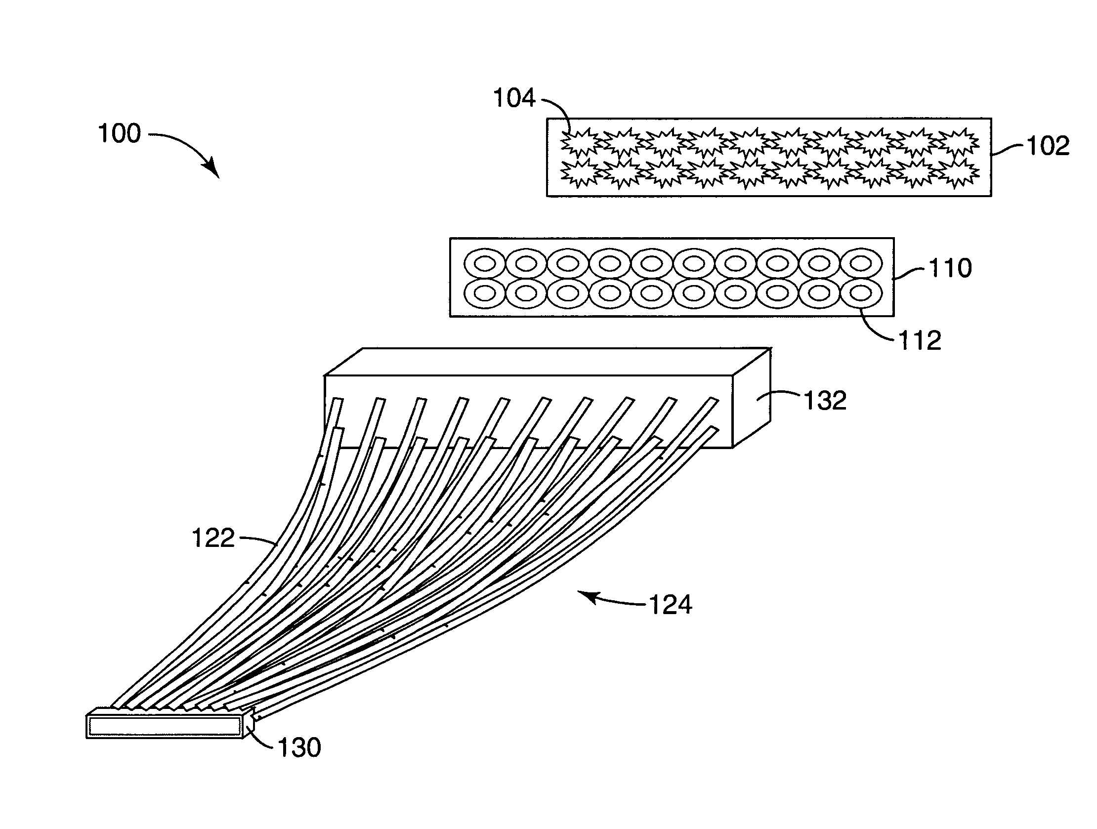
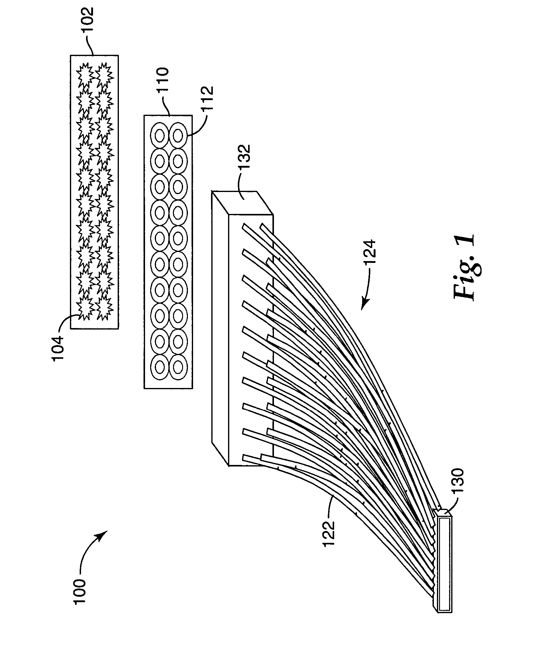
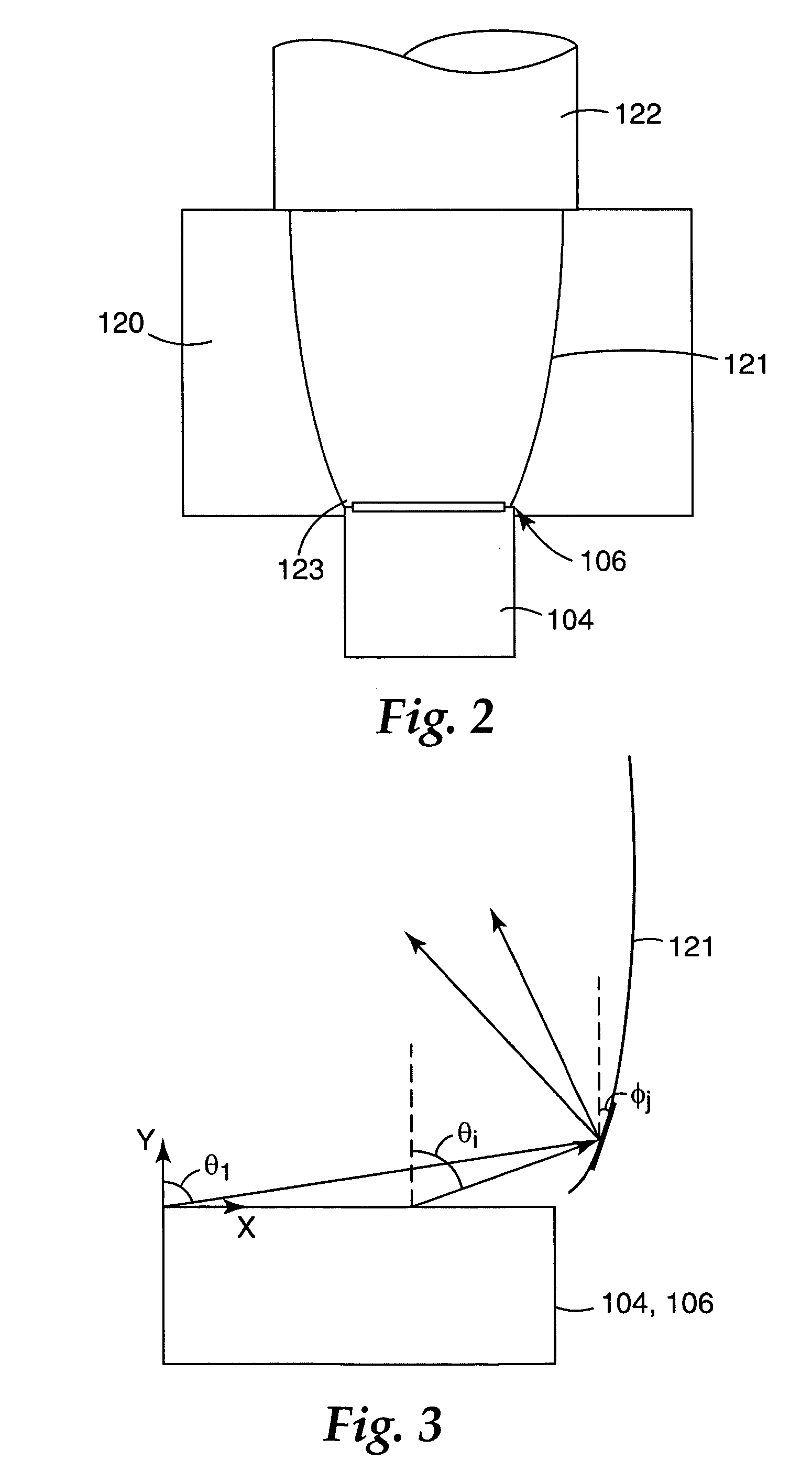
[0117]The illumination assemblies and systems described above have several advantages over prior systems. First, smaller LED dies, such as those described above, with lower heat outputs can be utilized without suffering loss in illumination intensity. In the examples discussed above, the LED dies in the array are physically separated to avoid thermal hot spots in the mounting structure. This structure allows the LED dies to be electrically driven harder, with more output illumination (and hence, a brighter output beam emitted from the output ends of the fibers). Tightly packing large numbers of LED die is a long term reliability concern since local heating, even with a globally efficient
thermal conduction mechanism, can cause reduced LED lifetime and in extreme cases catastrophic failures. Spacing the LED dies farther apart than the width of the LED die allows reasonably thermally conductive substrates to extract the heat from the
LED array without local hot spots. The LED dies may also be safely operated at higher currents and light outputs than stated in the normal operating specifications, if sufficient heat extraction is provided. Moreover, as compared to filament light sources, the LED die array of the present invention does not generate intense heating in the forward directed beam, which can be a result of filament heating. This intense heat can cause damage to
polymer lenses and reflector assemblies that are sometimes employed in lighting elements, such as automobile headlights.
[0118]A second
advantage is the one
fiber per LED
coupling. Prior systems coupled dense arrays of LEDs into a large
diameter fiber or
fiber bundle. Dense LED arrays have the previously mentioned reliability problems, but their implementation has been justified as providing the best efficiency for coupling light into the fiber (at the expense of reliability). Providing one fiber per LED source allows the LED dies to be physically separated, minimizing localized thermal effects from dense concentrations of LEDs as discussed above.
[0119]Another
advantage is the
electrical interconnect wiring. A thin (for example, 25 to 50
micrometer) layer of
electrical wiring as exemplified by flexible circuitry, such as the flexible circuitry described previously, provides
electrical interconnect, some
thermal conduction of heat from the die, and a flat
electrical interconnect structure which may be laminated. The resulting construction overall is a very
thin layer, so that the optical performance of this layer is not critical. The thin, flat layer allows the entire array to be laminated into a highly reliable
solid or nearly
solid block of material with the
LED array (on a substrate) bonded to the electrical interconnect layer, which can in turn be bonded to the reflector sheeting. The advantages of particular implementations of interconnect circuitry are described in the pending and co-owned application entitled “Illumination
Assembly” Ser. No. 10 / 727,220, incorporated by reference above.
[0120]An additional
advantage of the illumination devices described herein is the lamination or encapsulation of the entire
assembly. Since the
LED array and the reflector cavities may be filled with a
solid material, for example an
epoxy or molded
polycarbonate, the entire
assembly may be laminated into a block with no voids. Voids in
electrical equipment can be reliability issues in some applications because water tends to collect in
polymer voids, leading to long-term reliability issues.
[0124]Another advantage of the present invention is the ability to tailor the color spectrum emitted from the LED die array. While “white” light may be made from a combination of LED die colors, several exemplary embodiments utilize a
phosphor layer to convert blue or UV
radiation into a
broad spectrum, i.e., “white” light. Using different phosphors across the LED die array can produce “white” light with a desired
color temperature. Similarly, a variety of colors may be produced by tailoring the
phosphor used across the LED dies.
[0125]While placing the
phosphor-coated sheet on top of the reflector array may not result in the most efficient coupling of
light energy into a
fiber array (because of the limited acceptance angle of the
optical fiber), such a construction might be advantageous for a large surface, high
divergence array, again without localized hot spots from dense concentrations of LEDs.
[0126]While the present invention has been described with a reference to exemplary preferred embodiments, the invention may be embodied in other specific forms without departing from the scope of the invention. For example, while the present exemplary embodiments have been shown in the area of automotive headlights, the present illumination system may be used in aircraft, marine, medical, industrial, home, and even other automotive applications. Accordingly, it should be understood that the embodiments described and illustrated herein are only exemplary and should not be considered as limiting the scope of the present invention. Other variations and modifications may be made in accordance with the scope of the present invention.


