
Filter-integrated even-harmonic mixer and hi-frequency radio communication device using the same

a filter-integrated, even-harmonic technology, applied in the direction of modulation transference by distributed inductance and capacitance, transmission noise suppression, electrical equipment, etc., can solve the problems of increasing the cost of components and mounting process, and affecting the performance of even-harmonic mixers. , to achieve the effect of reducing the circuit scale per semiconductor chip that constitutes the filter-integrated even-harmonic mixer and reducing the cos

Active Publication Date: 2007-01-16
SHARP KK
View PDF14 Cites 10 Cited by
  • Summary
  • Abstract
  • Description
  • Claims
  • Application Information

AI Technical Summary

Benefits of technology

The present invention provides a filter-integrated even-harmonic mixer that simplifies the construction of a connection between an even-harmonic mixer and a high-frequency bandpass filter, reduces circuit size, and reduces cost of an associated semiconductor chip. The filter-integrated even-harmonic mixer has a transmission line with a length set so that impedance on the transmission line side viewed from the connection point between the even-harmonic mixer and the transmission line is roughly zero for a frequency of a local oscillation signal inputted to the even-harmonic mixer. This eliminates the need for an open stub for providing equivalent grounding for the frequency of the local oscillation signal. The circuit includes an anti-parallel diode pair and a short stub, and the impedance of the transmission line is significantly increased for a signal within the passband of the filter. The high-frequency bandpass filter has a microstrip resonator with a significantly increased impedance for signals within the passband. The filter-integrated even-harmonic mixer reduces the gain of an amplifier for outputting a desired transmission power, resulting in cost and power consumption reduction. The circuit is integrated on a semiconductor substrate, and the size and cost of the circuit are reduced.

Problems solved by technology

However, the aforementioned conventional even-harmonic mixer has the following problems.
That is, it is required to additionally connect a bandpass filter for allowing the high-frequency signal inputted to the high-frequency signal terminal 1 to pass, and this increases the costs of the components and of the mounting process.
Moreover, when the milliwave band frequency is very high, a loss at a connection between the even-harmonic mixer and the bandpass filter becomes significant, and the characteristic is deteriorated.
However, in such a case, if the higher harmonic mixer and the bandpass filter are separately designed and integrated by simply being arranged on a semiconductor chip and connected together by means of a transmission line of an appropriate length, the passive circuit of the open stub 10 and the short stub 11 of the even-harmonic mixer, the filters 6 and 7 and so on disadvantageously will occupy the greater part of the area.
Accordingly, there is a problem that the area of the semiconductor chip is increased and the unit price of the semiconductor chip is raised.

Method used


Image

  • Filter-integrated even-harmonic mixer and hi-frequency radio communication device using the same
  • Filter-integrated even-harmonic mixer and hi-frequency radio communication device using the same
  • Filter-integrated even-harmonic mixer and hi-frequency radio communication device using the same

Examples


first embodiment

[0041](First Embodiment)

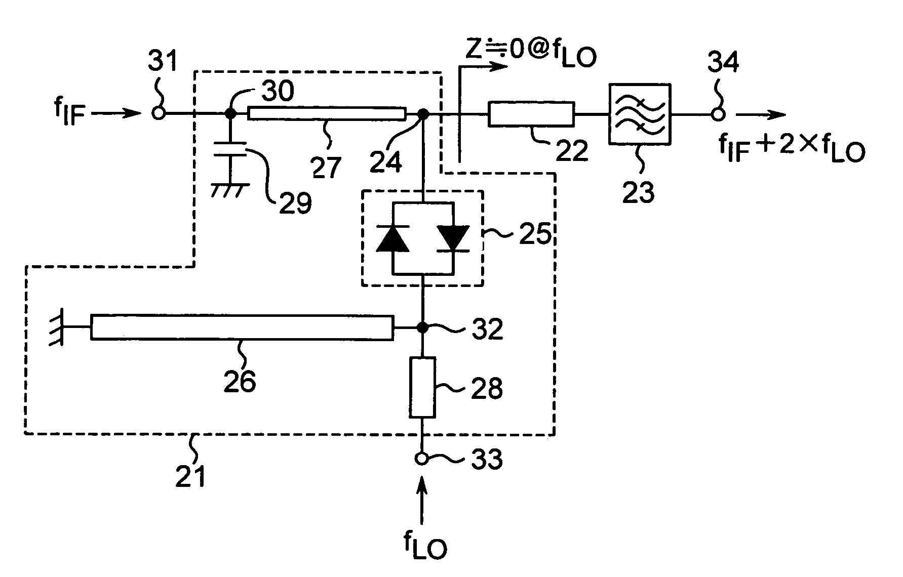
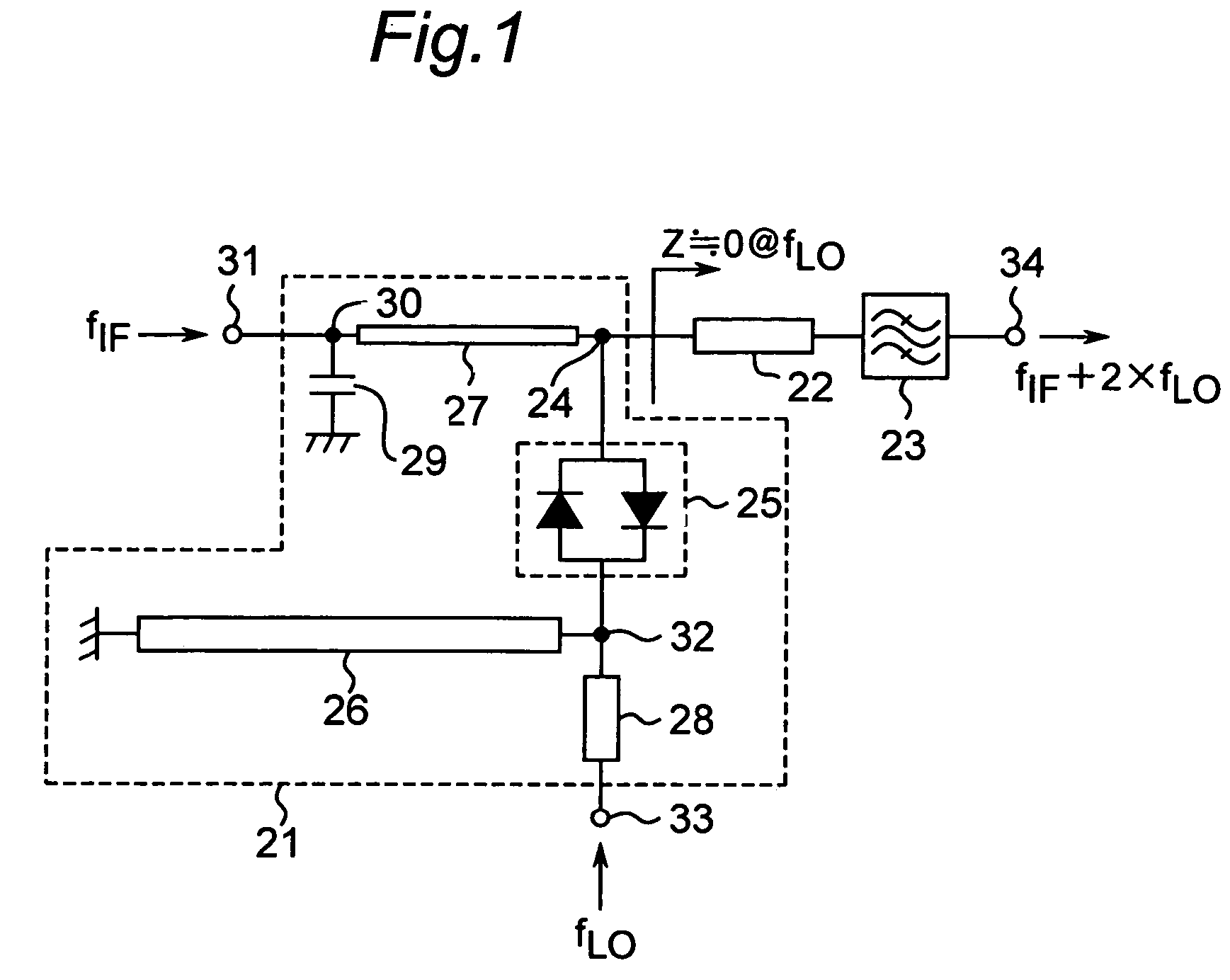
[0042]FIG. 1 is a diagram showing the construction of the filter-integrated even-harmonic mixer of the present embodiment. In this case, reference is made on the basis of an example of an even-harmonic mixer for an upconverter that receives an intermediate frequency signal (having a frequency fIF) and a local oscillation signal (having a frequency fLO) as inputs thereto and outputs a high-frequency signal (frequency fRF) of a frequency obtained by mixing double the frequency fLO with the frequency fIF. That is, the frequency fRF, the frequency fIF and the frequency fLO have the following relationship:

fRF=2×fLO+fIF.

[0043]The present filter-integrated even-harmonic mixer is constructed of an even-harmonic mixer 21, a transmission line 22 and a high-frequency bandpass filter 23. The even-harmonic mixer 21 and one end of the high-frequency bandpass filter 23 are connected to each other via a transmission line 22. Moreover, the length of the transmission line 22 i...

second embodiment

[0071](Second Embodiment)

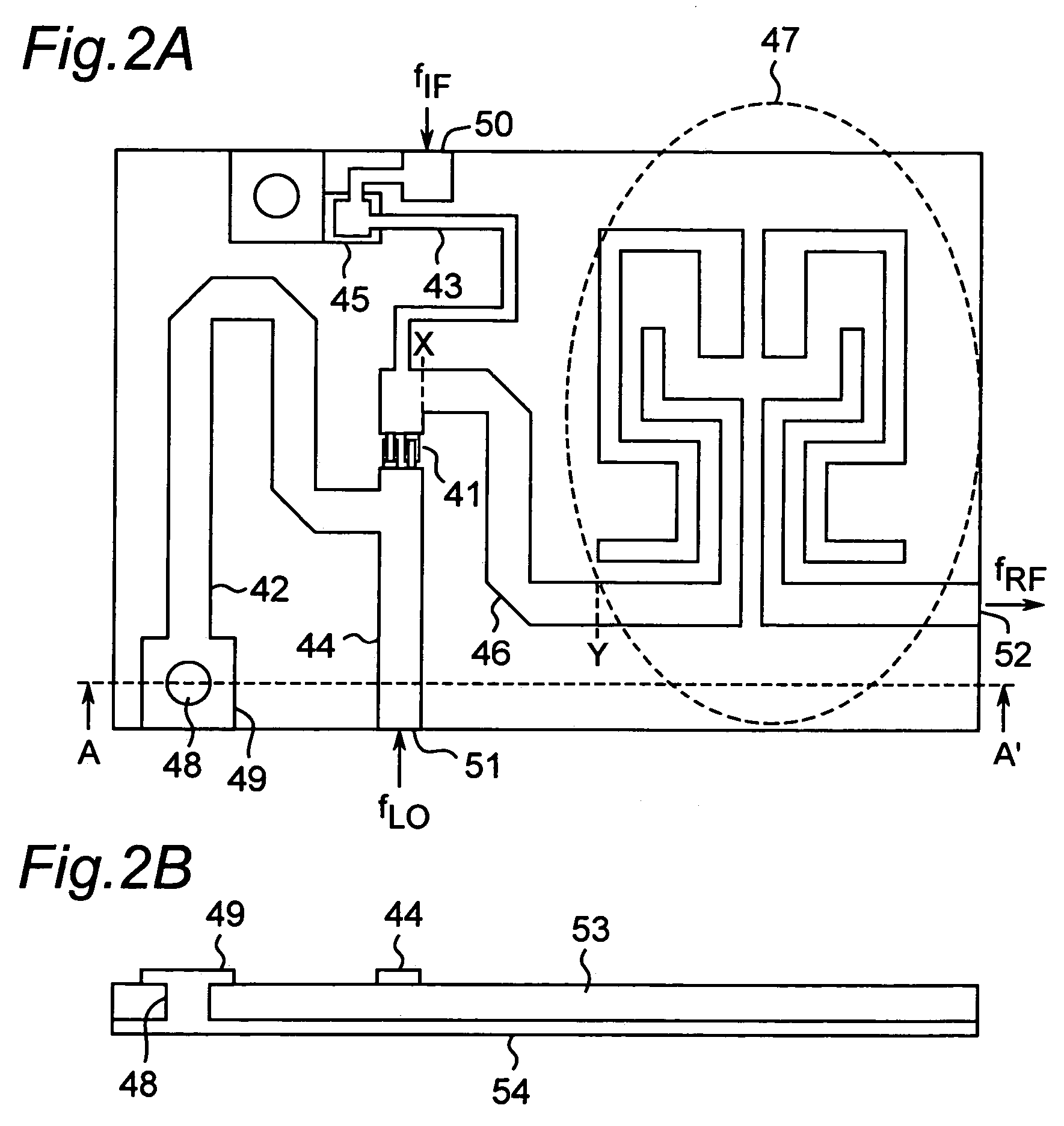
[0072]FIG. 7 is a diagram showing the construction of the filter-integrated even-harmonic mixer of the second embodiment. The present filter-integrated even-harmonic mixer is essentially the same as the filter-integrated even-harmonic mixer described in connection with the first embodiment. That is, an even-harmonic mixer 81, a transmission line 82, a high-frequency bandpass filter 83, an anti-parallel diode pair 84, a short stub 85, an intermediate frequency signal transmission line 86, a local oscillation signal transmission line 87, a capacitor 88, an intermediate frequency signal terminal 89, a local oscillation signal terminal 90 and a high-frequency signal terminal 91 are the same as the even-harmonic mixer 21, the transmission line 22, the high-frequency bandpass filter 23, the anti-parallel diode pair 25, the short stub 26, the intermediate frequency signal transmission line 27, the local oscillation signal transmission line 28, the capacitor 29, the...

third embodiment

[0074](Third Embodiment)

[0075]The present embodiment relates to a high-frequency radio communication device that employs the filter-integrated even-harmonic mixer of the first or second embodiment for a transmitter and a receiver. FIG. 8 is a block diagram of the present high-frequency radio communication device. In FIG. 8, a transmitter 101 is constructed of a modulation signal source 103, a filter-integrated even-harmonic mixer 104, a power amplifier 105, an antenna 106 and a local oscillation signal source 107. The filter-integrated even-harmonic mixer 104 is constructed of an even-harmonic mixer 108 as an upconverter, a transmission line 109 and a high-frequency bandpass filter 110. Moreover, a receiver 102 is constructed of a tuner 111, a filter-integrated even-harmonic mixer 112, a low-noise amplifier 113, an antenna 114 and a local oscillation signal source 115. The filter-integrated even-harmonic mixer 112 is constructed of an even-harmonic mixer 116 as a down converter, a t...


PUM


Abstract

Configuration of a connection between an even-harmonic mixer and a filter is simplified, thereby enabling size reduction. An even-harmonic mixer and a high-frequency bandpass filter are connected to each other via a transmission line, thereby forming a filter-integrated even-harmonic mixer. The length of the transmission line is set so that impedance on the transmission line side as viewed from a connection point between the even-harmonic mixer and the transmission line is approximately 0 for a frequency fLO of a local oscillation signal. This allows elimination of an open stub which is used in a conventional even-harmonic mixer and of which the line length to provide equivalent grounding for the frequency fLO is about 1 mm. Thus, the connection portion between the even-harmonic mixer and the high-frequency bandpass filter is simplified and a compact circuit layout for the filter-integrated even-harmonic mixer is obtainable.

Description

[0001]This application is the U.S. national phase of International Application PCT / JP02 / 11098 filed Oct. 25, 2002, which designated the U.S. PCT / JP02 / 11098 claims priority to JP Patent Application No. 2001-336573 filed Nov. 1, 2001. The entire contents of these applications are incorporated therein by reference.TECHNICAL FIELD[0002]The present invention relates to a filter-integrated even-harmonic mixer in which an even-harmonic mixer for use in a microwave millimeter wave communication device and a high-frequency bandpass filter are connected to each other via a transmission line, and also to a high-frequency radio communication device employing the mixer.BACKGROUND ART[0003]FIG. 9 shows a structure of a conventional even-harmonic mixer disclosed in, for example, JP Patent No. 2795972. This even-harmonic mixer is an example of the even-harmonic mixer for a down converter that receives a high-frequency signal (having a frequency frf) and a local oscillation signal (having a frequenc...

Claims


Application Information

Patent Timeline
Patent Type & Authority Patents(United States)
IPC IPC(8): H04B1/26H03D9/06
CPCH03D9/0633
Inventor YAMADA, ATSUSHIAMANO, YOSHIHISAMOTOUCHI, YOSHINORI
Owner SHARP KK
Learn More