High throughput separations based analysis systems

a technology of analysis system and high throughput, applied in the direction of diaphragm, fluid speed measurement, electrolysis, etc., can solve the problems of slow system throughput and labor intensive operation, conventional slab gel electrophoresis is a very time-consuming and labor-intensive process, and can take up to several hours to complete the process, so as to achieve high flow resistance and high flow resistance. , the effect of high flow resistan

Inactive Publication Date: 2007-01-30
CAPLIPER LIFE SCI INC
View PDF27 Cites 118 Cited by
  • Summary
  • Abstract
  • Description
  • Claims
  • Application Information

AI Technical Summary

Benefits of technology

[0063]As described above, the present invention also permits the bulk loading of sample material without causing excessive displacement of the separation matrix. This would be substantially impossible in conventional capillary systems where any sample material bulk flowed into a capillary would necessarily displace a similar volume of separation matrix. Similarly, in microfluidic devices previously described for performing separation applications (see, e.g., Woolley and Mathies, Proc. Nat'l Acad. Sci. USA, 91:11348–11352(1994)), electrophoretic sample loading was used. In these previously described systems, if a sample were pressure loaded, it would substantially disrupt and displace the separation matrix within the separation channel portion of the device.
[0064]In the devices of the present invention, displacement of the separation matrix during bulk sample loading is typically carried out by providing a sufficient flow resistive barrier between the sample loading conduit and the separation conduit. This barrier may be embodied in the configuration of the separation channel as a whole, e.g., providing the separation conduit with a sufficiently high flow resistance to substantially resist bulk flow pressures in the sample loading channel, either positive or negative. Alternatively, the barrier is provided in an injection conduit that links the separation conduit and the sample loading conduit. In particular, the injection conduit that links the sample loading conduit and the separation conduit may be provided with a sufficiently high flow resistance to resist bulk flow between the sample loading and separation conduits.
[0065]As noted herein, flow resistances in channel structures are typically varied by altering the cross-sectional area of the channel and/or varying the channel's length, where a smaller cross-sectional area or longer channel length will give rise to a higher flow resistance. Variation of channel lengths typically involves simply altering the channel's course to increase or decrease its length. Similarly, channel cross-sectional areas are typically varied by fabricating the channels shallower, deeper or wider. Advantageously, one can substantially alter the bulk flow or hydrodynamic resistance of a channel, without substantially altering the electrical resistance of that channel, which electrical resistance will affect the amount of current that is passed through the channel, e.g., in electrophoretic injection and separation within the devices described herein. In particular, in microscale channels having aspect ratios (width:depth) of greater than about 5, the hydrodynamic resistance of the channel is a function of the cube of the channel depth, while the electrical resistance is related linearly to ...

Problems solved by technology

While conventional technologies have been developed that are able to perform these separations based analyses, and in some cases at reasonably high rates, these systems still suffer from slower than optimal throughput and labor intensive operation.
For example, conventional slab gel electrophoresis is a very time consuming and labor intensive proc...

Method used


Image

  • High throughput separations based analysis systems
  • High throughput separations based analysis systems
  • High throughput separations based analysis systems

Examples


example 1

Chip Design and Fabrication

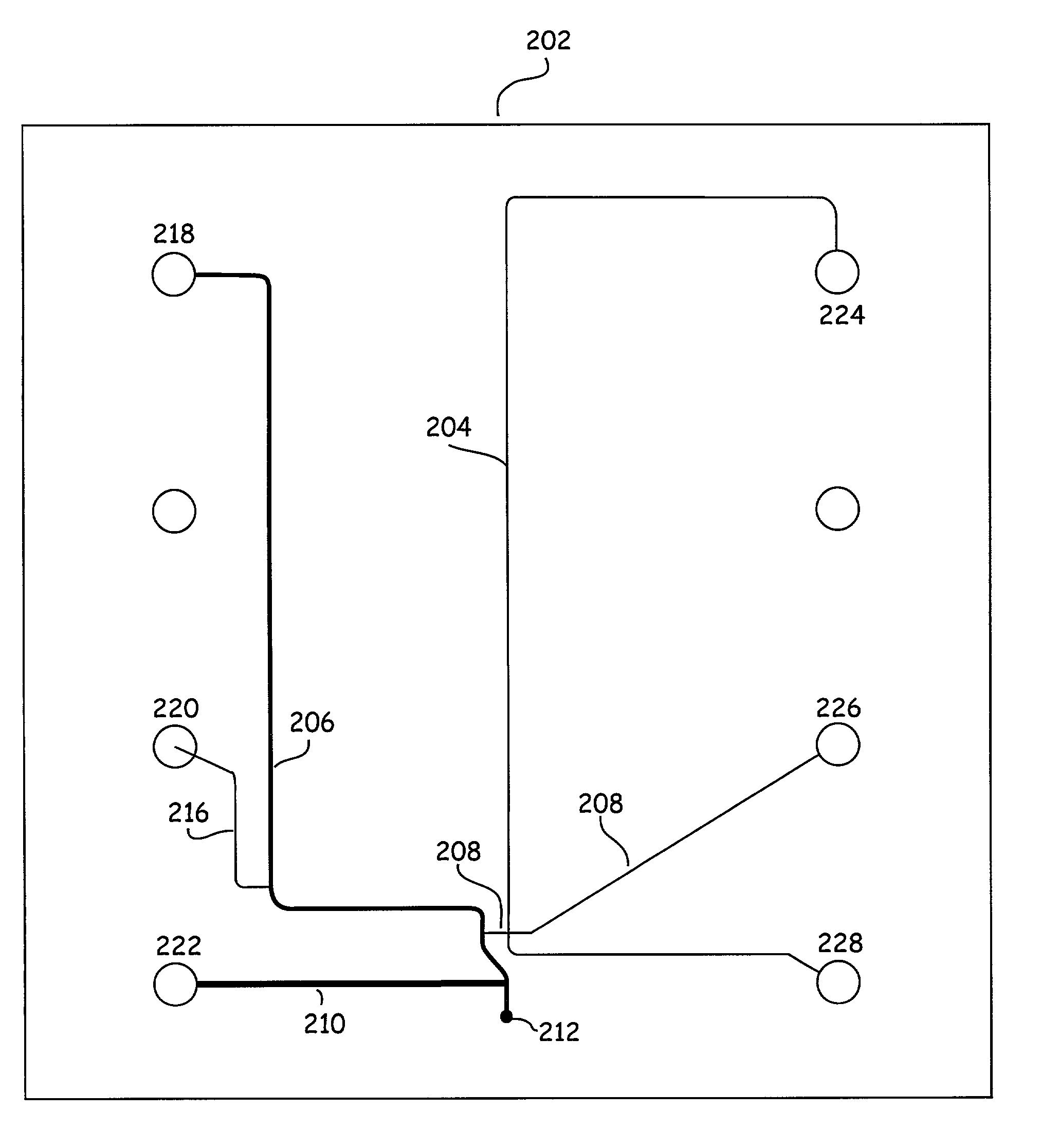
[0078]A microfluidic device having a channel and reservoir configuration illustrated in FIG. 2 was fabricated from a pair of planar glass substrates. In particular, a first substrate was etched to provide the various channels of the device. Channels 206 and 210 were etched to a depth of approximately 20 μm, with channel 206 having a width (at the top of the channel) of approximately 90 μm while channel 210 had a width of approximately 165 μm. Channel 204, 208 and 216 were etched to a depth of approximately 7 μm and widths of approximately 24 μm. The overall length of the separation channel 204 was 56 mm, while the injection channel 208 was 15.6 mm in overall length which included a 0.5 mm segment connecting the separation channel to the sample loading channel 206. The sample loading channel 206 had an overall length of 39.6 mm, while the reagent introduction channel 210 had a length of 13.2 mm and the electrical connecting channel 216 was 8.9 mm long. Rese...

example 2

Serial Separations-Based Analysis

[0079]The device shown in FIG. 2 was used to perform a number of serial DNA separations by bulk loading sample material into the sample loading channel, injecting a small fraction of that material into the separation channel that included a separation medium, and electrophoretically separating the material.

[0080]All reagents were taken from a DNA 7500 LabChip® kit, commercially available from Agilent Technologies. The separation medium included a mixture of a sieving polymer solution and DNA intercalating dye. Internal DNA marker standards (DNA Markers) contained a 15 bp and 2000 bp DNA fragments, each at a concentration of 5 ng / μl. The DNA ladder, used to generate a standard curve against which sample data was measured, included fragments of 50 bp, 100 bp, 500 bp, 700 bp and 1000 bp, where each fragment was present at a concentration of 4 ng / μl.

[0081]The microfluidic device was prepared by adding 25 μl of the separation medium to reservoirs 220, 224...

example 3

Post Separation Dilution for Protein Separations

[0083]The device shown in FIG. 3C was used to perform a protein separation where a post separation dilution operation is performed prior to detection. The device was loaded with a separation matrix that was made up of 3.25% polydimethylacrylamide co-acrylic acid with 0.25% SDS and syto 60 dye 1t 4 μM, in 0.12 mM tricine buffer. The separation matrix was loaded into reservoirs 370, and 374–382 and these wells were pressurized using a syringe for 4 minutes each to drive the matrix through the channels of the device. The matrix mixture in wells 380 and 382 was removed and replaced with matrix that lacked SDS and dye.

[0084]The sample for separation was a Bio-Rad standard protein ladder (#148–2015) that had been diluted 3× in PBS. Fifty μl of the diluted ladder was mixed with 25 μl of sample buffer (4% SDS, 10 mM tricine, 3.5 mM Tris) and heated to 100 ° C. for 5 minutes. After heating, the samples were diluted with 150 Ml of water and the ...


PUM

PropertyMeasurementUnit
Fractionaaaaaaaaaa
Fractionaaaaaaaaaa
Fractionaaaaaaaaaa

Abstract

Devices, systems and methods for use in separating sample materials into different fractions that employ bulk fluid flow for loading of samples followed by electrophoretic separation of the sample material. Devices employ configurations that optionally allow bulk sample loading with some or no displacement of a separation matrix within a separation conduit. Methods of using these devices, and systems that incorporate these devices are also envisioned.

Description

RELATED APPLICATIONS[0001]This application claims priority to U.S. Provisional Patent Application Nos. 60 / 327,566, filed May 17, 2001, 60 / 222,491, filed Aug. 2, 2000, and 60 / 276,731, filed Mar. 16, 2001. The entire disclosure of each of these applications is hereby incorporated herein by reference in its entirety for all purposes.BACKGROUND OF THE INVENTION[0002]Separations based analyses are a prominent part of biological research, allowing one to characterize different biological samples, reaction products and the like. Examples of some of the more prevalent separations based analyses include electrophoretic separations of macromolecular species, e.g., proteins and nucleic acids. While conventional technologies have been developed that are able to perform these separations based analyses, and in some cases at reasonably high rates, these systems still suffer from slower than optimal throughput and labor intensive operation. For example, conventional slab gel electrophoresis is a v...

Claims


Application Information

Patent Timeline
IPC IPC(8): G01N27/26G01N33/48B81B1/00G01N27/447G01N33/483G01N37/00
CPCG01N27/44791G01N27/44743
Inventor AUSSERER, WALTERBOUSSE, LUC J.DUBROW, ROBERT S.SUNDBERG, STEVEN A.CHOW, ANDREA W.WANG, BENJAMIN N.
Owner CAPLIPER LIFE SCI INC
Why Eureka
Try Eureka