Variable valve system of internal combustion engine and hydraulic actuator

a technology of hydraulic actuator and internal combustion engine, which is applied in the direction of machines/engines, non-mechanical valves, output power, etc., can solve the problems of not being able to freely control the timing and degree of opening of suction and exhaust valves, stepping control is possible, and types tend to be excessively large or heavy, so as to facilitate the manufacturing process of hydraulic pistons and simplify the structure of slots. , the effect of reducing the landing speed of the valv

Inactive Publication Date: 2007-02-20
YOKOHAMA TLO
View PDF11 Cites 7 Cited by
  • Summary
  • Abstract
  • Description
  • Claims
  • Application Information

AI Technical Summary

Benefits of technology

[0019]A mode of carrying out the hydraulic pressure release control valve in the invention according claim 1 described above can be a solenoid controlled pilot operated valve (invention according to claim 2) or an electro-hydraulic proportional control valve (invention according to claim 3) in relation to the variable control of the valve lift mentioned below. In any case, according to the mode of carrying out mentioned above, the position of the hydraulic piston can be controlled freely by electric signals.
[0020]Then, as inventions wherein the hydraulic actuator described above is applied to a variable valve system of internal combustion engine, claims 4–7 described below are preferable. In other words, a variable valve system of internal combustion engine for opening and closing a suction valve for aspirating gas into the internal combustion engine and an exhaust valve for exhausting combustion gas by a hydraulic actuator through a coupling and a spring for the valve, and for variably controlling the opening and closing timing and the opening and closing time of said valve, wherein the hydraulic actuator according to said claim 1 or claim 2 is used as said hydraulic actuator, and said valve is variably controlled by controlling said hydraulic pressure release control valve (invention according to claim 4). According to this structure, it is possible to provide a cam-less and sensor-less variable control system cable of reducing power consumption and of improving response speed as compared with the prior systems.
[0023]And in the variable valve system according to claim 6, the structure of the gradually decreasing the cross sectional area of said slot consists of gradually changing the groove depth of the slot while the groove width is kept constant (invention according to claim 7). This will simplify the structure of the slot and facilitates the manufacturing process of the hydraulic piston having the slot.
[0024]And as for the invention for the control method of variable valve system, the invention according to claim 8 described below is preferable. Specifically, in the control method of variable valve system described in the claim 4 or 5, for the closing operation of said valve, said hydraulic pressure release control valve is switched from OPEN to CLOSE followed by at least another operation of opening and closing the hydraulic pressure release control valve to close said valve (invention according to claim 8). This will enable to control landing at a reduced speed wherein the landing speed of the valve is further reduced, and to further reduce the noise of valve operation as described in details further below.

Problems solved by technology

As the valves governing the suction and exhaust of the internal combustion engine have been driven by a crank shaft in the prior system, it has not been possible to freely control the timing and degree of opening of suction and exhaust valves.
In this case, however, only stepped control is possible.
However, these types tend to be excessively large or heavy and are not so practical (see for example Patent Documents 1 and 2).
In the case of the prior devices, for example in the case of the device described in the Non-Patent Document 1, due to the use of a simple hydraulic piston, the mounting of a displacement meter for electric position sensors and the use of the servo-valve (two-stage type, nozzle flap valve and spool valve) with a low motive power efficiency of 33% at the maximum for control, the power consumption of the servomechanism is large, and due to a limit in responsiveness, the whole device was able to cope with an engine speed of approximately 2,000 rpm.
Furthermore, electric sensors were problematic because of strong vibrations and reliability of their operation at a high temperature, and these problems constituted a bottleneck for their actual use.

Method used


Image

  • Variable valve system of internal combustion engine and hydraulic actuator
  • Variable valve system of internal combustion engine and hydraulic actuator
  • Variable valve system of internal combustion engine and hydraulic actuator

Examples


Embodiment Construction

[0050]We will now describe the mode of carrying out and an embodiment of the present invention with reference to drawings.

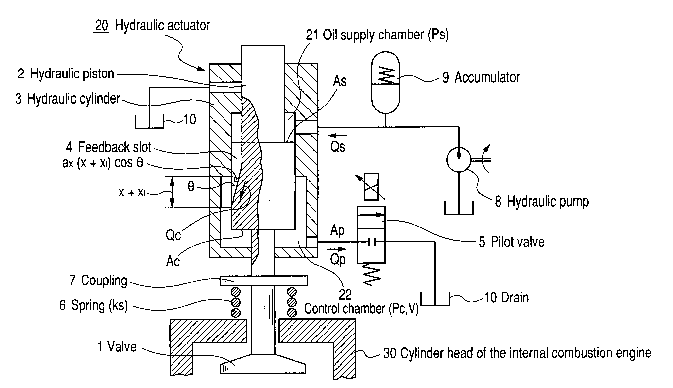
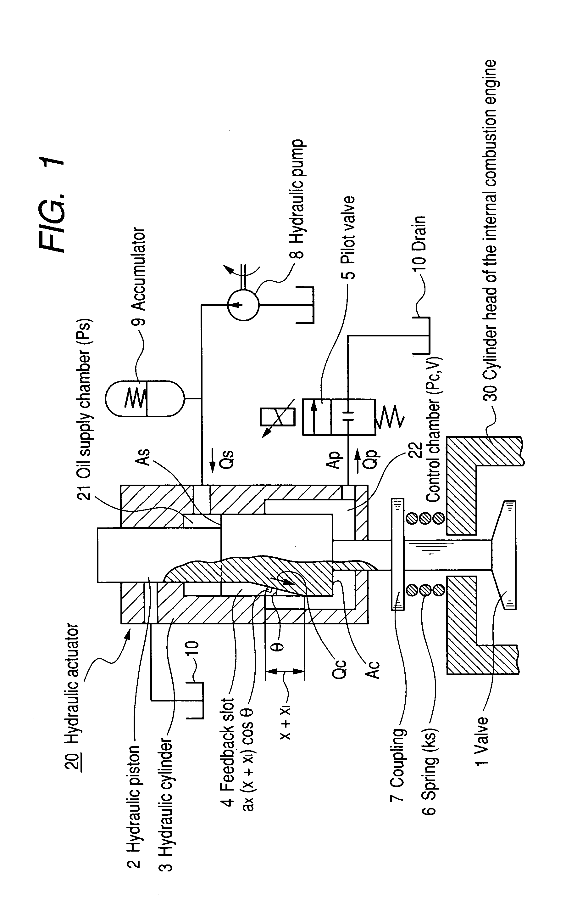
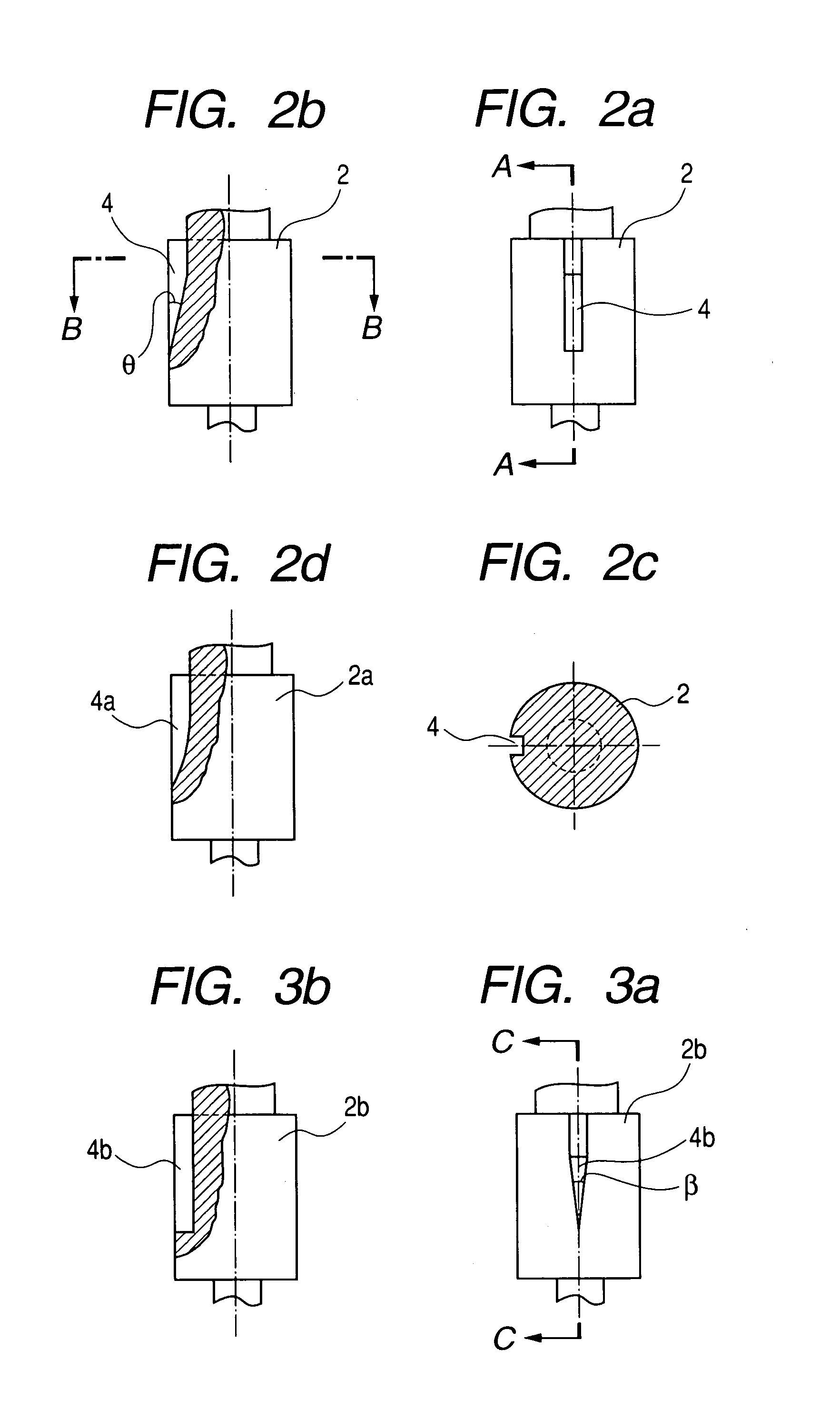
[0051]FIG. 1 is a schematic diagram describing the working principle of the variable valve system for internal combustion engine and the hydraulic actuator according to the present invention. FIG. 2 is a partially cutaway view of an embodiment of hydraulic piston showing, for the convenience of description, a considerably enlarged view of the groove width of the feedback slot shown in FIG. 1, and FIG. 3 is a partially cutaway view of another embodiment of hydraulic piston different from FIG. 2.

[0052]In FIG. 1, the code 1 represents a valve (the main valve for controlling the suction into and exhaust from the engine), 2 represents a hydraulic piston (the hydraulic piston for operating the valve 1), 3 represents a hydraulic cylinder (the cylinder fitting the hydraulic piston 2), 4 represents a feedback slot (channel for controlling the flow rate of oil according to...


PUM


Abstract

In a hydraulic actuator comprising a hydraulic piston, a hydraulic cylinder and a hydraulic pressure source wherein said hydraulic piston has a larger area exposed to pressure on the side of the control chamber than on the side of oil supply chamber of said hydraulic cylinder, wherein said hydraulic piston has, in its outer peripheral part, a slot connecting said oil supply chamber side with the control chamber side in the direction of shaft and the cross sectional area of the slot in the direction of said shaft changes according to the displacement of the hydraulic piston in the direction of its shaft, and the control chamber has a pilot valve, the suction and exhaust valve in a variable valve system of the internal combustion engine are opened and closed by said hydraulic actuator through a coupling and springs for the valve, for variably controlling the opening and closing timing, the opening and closing time, and the lift of the valve, whereby it is possible to provide a variable valve system for internal combustion engine that is a cam-less and sensor-less, and a hydraulic actuator that enable to reduce power consumption and to improve response speed, and to control landing speed so that a smooth landing may be realized.

Description

TECHNICAL FIELD[0001]The present invention relates to a hydraulic actuator and a variable valve system of internal combustion engine and a method of controlling the same wherein the suction valve and exhaust valve of an internal combustion engine are opened and closed by the hydraulic actuator.BACKGROUND ART[0002]The hydraulic actuator is used in machine tools and for other industrial uses in general as well as in driving devices of suction and exhaust valves of internal combustion engines. As the valves governing the suction and exhaust of the internal combustion engine have been driven by a crank shaft in the prior system, it has not been possible to freely control the timing and degree of opening of suction and exhaust valves.[0003]LPG and CNG (compression natural gas) engines on which much expectation has been entertained as alternative engines in recent years suffer from strong knockings especially while they are running at a high speed. In order to solve this problem, the meth...

Claims


Application Information

Patent Timeline
Patent Type & Authority Patents(United States)
IPC IPC(8): F01L9/02F01L9/10F02D13/02
CPCF01L9/02F02D13/0207F02D13/0253F01L2800/00Y02T10/18F01L2820/01Y02T10/12F01L9/10F15B15/14F02D13/02
Inventor TANAKA, HIROHISA
Owner YOKOHAMA TLO
Why Eureka
Try Eureka