[0046]Shortcomings of other projection systems and of the Christie and Barco 3D DLP
projection system include the fact that the
projector output is synchronized to the input. This means that the rate at which the
projector displays the sequence of left and right images is the same is the input vertical
synchronization signal. The result is that in order to reduce or eliminate
flicker in the projected image, the input image source must be driven at a very
high frame rate. An
advantage of the present invention over prior art systems is that the input frame rate and the output frame rate can be completely decoupled, eliminating the need for expensive high-end
computer equipment required to generate the high frame-rate images.
[0047]There are several brands of off-the-shelf DLP projection systems that have been found to support a form of “page-flipped” 3D output without any modifications. To view stereoscopic 3D images with such projectors, a pair of
liquid crystal shutter glasses may be synchronized to the video input source or to the RGB computer input source. The major shortcoming of this solution is that the maximum input frame rate for the RGB computer input is typically 85 Hz (42.5 Hz per eye) and is not high enough to avoid noticeable
flicker. This fact is also true for the video input that is fixed at around 60 Hz (30 Hz per eye). Another shortcoming is the fact that the flicker rate of the output is dependent on the input data frame rate.The Problem
[0048]The fundamental problem of
stereoscopic imaging is the display of two perspective images in such a way that they appear simultaneous to an observer and in such a way that the each eye sees only the corresponding perspective image. There are many systems in existence that provided this capability for stereo viewing by various different methods. The problem solved by this invention is the display of high-quality 3D stereoscopic images using a digital micro-mirror based optical system. Further, the present invention provides a means and apparatus to interpolate 3D image data from any input signal resolution to the
display resolution without corruption due to the mixing of left-right perspective image data. All major stereoscopic data formats are supported. Further the present invention provides a system whereby 3D image decoding may be accomplished through one of three different
decoding methods including passive linearly polarized
eyewear, passive circularly polarized
eyewear, active
shutter glass
eyewear or color filter based glasses. In the preferred embodiment the user may switch between any of the 3D optical encoding methods by simply changing an external filter
assembly.
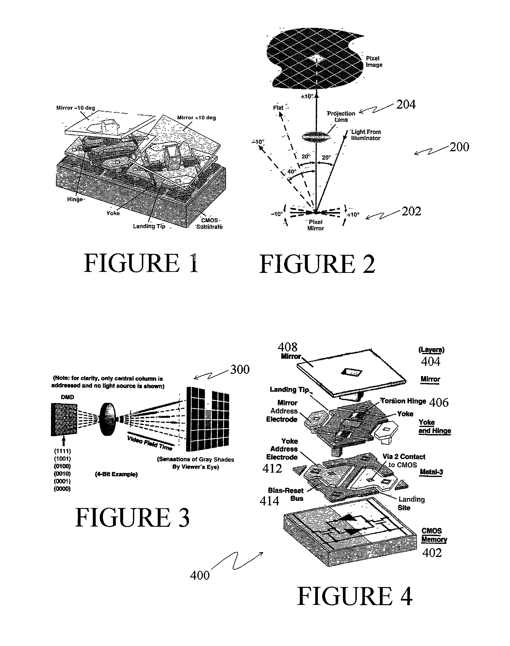
[0049]Micro-mirror display technology (such as that developed by Texas Instruments) as discussed above is well suited to stereoscopic display because of its
fast switching times and extremely low persistence compared to
liquid crystal based display technologies such as polysilicon, DILA™ (
digital image light
amplifier), and LCOS (
liquid crystal on
silicon). These properties that are inherent to DMD technology help to reduce stereoscopic
crosstalk (the observed light leakage between left and right perspective views) in ways that are not possible by other 3D methods. Further, unlike some other 3D methods this invention permits the operation of the 3D
projector in both stereoscopic and non-stereoscopic
modes without any physical hardware or
software changes required in switching between the two viewing methods. In addition to the 3D enhancements to DMD projectors, one aspect of the invention also has the capability of enhancing the brightness of 3D projection systems. This benefit is derived from the
cholesteric liquid crystal reflective coatings used on certain color wheels variations and used as a stand-alone polarization plate.BRIEF SUMMARY OF THE INVENTION
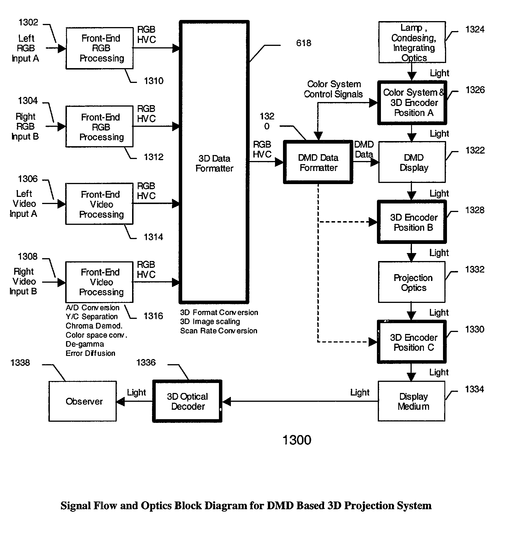
[0050]The invention has two main embodiments, a first called
column switching and blanking and a second embodiment called column doubling. The first embodiment is a projector for displaying a stereoscopic image with projector using one or more digital micromirror devices positioned into a plurality of columns and rows. The projector itself includes a
light source, an optical system, a
video processing system and a
data system for driving the micromirror devices. The data subsystem provides separate data to a plurality of column pairs of the micromirrors. The projector includes a stereoscopic
control circuit having a first state of the
control circuit for inputting a first eye view of the stereoscopic image and causing the micromirrors of a first column of each column pair to be in various on and off states during said first eye view of said stereoscopic image and for causing all of said micromirrors of a second column of each column pair to be in an off state during said first eye view of said stereoscopic image. A second state of the
control circuit is used for inputting a second eye view of the stereoscopic image and causes the micromirrors of the second column of each column pair to be in various on and off states during the second eye view of the stereoscopic image and for causing all of the micromirrors of the first column of each column pair to be in an off state during the second eye view of said stereoscopic image.
[0051]The second embodiment is a projector for displaying a stereoscopic image with the projector using one or more digital micromirror devices positioned into a plurality of columns and rows The projector includes a
light source, an optical system, a
video processing system and a
data system for driving said micromirror devices. The data subsystem provides separate data to a plurality of column pairs of the micromirrors. The projector includes a stereoscopic control circuit having a first state for inputting a first eye view of the stereoscopic image and causing each micromirror of each column pair to be in various but identical on and off states during said first eye view of said stereoscopic image. A second state of the control circuit for inputs a second eye view of the stereoscopic image and causes each micromirror of each column pair to be in various but identical on and off states during the second eye view of the stereoscopic image.

