Electrolytic commercial production of hydrogen from hydrocarbon compounds

a hydrocarbon compound and hydrogen technology, applied in the field of electrolytic commercial production of hydrogen from hydrocarbon compounds, can solve the problems of further development being likely curtailed and the diaphragm cell would have suffered further

Inactive Publication Date: 2007-02-27
RODOLFO ANTONIO M GOMEZ
View PDF8 Cites 50 Cited by
  • Summary
  • Abstract
  • Description
  • Claims
  • Application Information

AI Technical Summary

Benefits of technology

[0030]The electrolyte is preferably a mixture of water and acid such as sulfuric acid or phosphoric add containing multi-valent catalyst ions such as iron, copper, cesium, vanadium or oxidising ions such as chlorine or bromine compounds. The electrolyte may also contain modifiers such as surfactants to allow greater wetting of the electrode surfaces and increased aerophobic properties of the electrode surface so that gas bubbles formed on the electrode surface particularly at the cathode do not interfere with the electrolytic reaction.
[0032]Concentric cylindrical cells where the anode or cathode is the outer cylinder and the solution electrode is the inner cylinder may be used for small plants up to 5 kilowatt capacity, however, cubical cells with a centre circulating well fitted with an impeller for agitation are preferred for large capacity electrolytic cells as shown on FIG. 3. One set of electrodes on either side of the circulating well is installed. At the anode cell, the electrodes will alternate between solution electrode and anode electrodes. Similarly, solution electrodes and cathode electrodes alternate at the cathode cell. The circulating slurry and the action of the impeller maintain the coal particles in suspension, provide good mixing of the electrolyte at the electrode surface to minimize over-voltage, and provide good contact between the catalyst ions in the electrolyte and the coal particles.
[0033]The electrolyte may be alkaline or acidic but the preferred electrolyte is mixtures of sulfuric acid or phosphoric acid and water. Laboratory tests have shown that the conductivity of the electrolyte increases with temperature up to the boiling point of the electrolyte. The electrolyte temperature may be maintained at up to 160 degrees Celsius and the pressure may be maintained at up to 50 bars pressure. These conditions will reduce the electrode over-voltage substantially and the impedance of the electrolyte between electrodes including the effect of the gas bubbles on impedance. Modifying agents such as surfactants may also be added to the electrolyte to improve wetting of the surface of the electrodes. At the cathode electrode, modifying agents will make the surface of the electrode aerophobic to separate gas bubbles from the electrode surface faster to allow the maximum area of the cathode electrode available for reaction. Modifiers in the electrolyte may also play a reducing role at the cathode cell similar to their oxidising role at the anode cell.
[0037]A bleed solution may be taken to remove impurities that tend to build up in the electrolyte. Simple methods such as evaporation and cooling may be the most effective and low cost methods. Purified electrolyte is returned to the main circuit.
[0039]An alternate method of carrying out the process is to oxdize the electrolyte only and this is mixed with the coal in a separate leaching or reaction vessel where the oxidation of the coal is carried out as shown on FIG. 4. The coal may be in a fixed bed or as an agitated slurry of fine coal. After liquid-solid-gas separation the clear anolyte is passed to the cathode cell where the hydrogen ion is reduced to hydrogen gas. This may offer benefits such as lower pressure in the anode cells resulting in savings on capital cost.
[0040]There may be provided microwave energy into the separate leaching or reaction vessel to assist with the reactions in the separate leaching or reaction vessel. The purpose of this addition to the process is to ensure a fast reaction rate during leaching and assurance that the catalyst ions in the electrolyte are used up in the coal leaching step to prevent the consumption of electrons by the catalyst ions at the cathode as this would lead to lower electrical efficiency of the process. The microwave energy may be applied at 800 to 22,000 megahertz and it may be applied at a steady state or the microwave energy may be pulsed into the coal slurry.

Problems solved by technology

The electrolysis of coal has been reported since about the early nineteen thirties but further development was probably curtailed by the use of the diaphragm type electrolytic cell that has high impedance and low reaction rates.
The diaphragm cell would have suffered further when coal particles and reaction by-products such as tar fouled up the diaphragm.
A further handicap of the production of electrolytic hydrogen from coal is that one Faraday of electricity will produce only one gram of hydrogen.

Method used


Image

  • Electrolytic commercial production of hydrogen from hydrocarbon compounds
  • Electrolytic commercial production of hydrogen from hydrocarbon compounds
  • Electrolytic commercial production of hydrogen from hydrocarbon compounds

Examples


Embodiment Construction

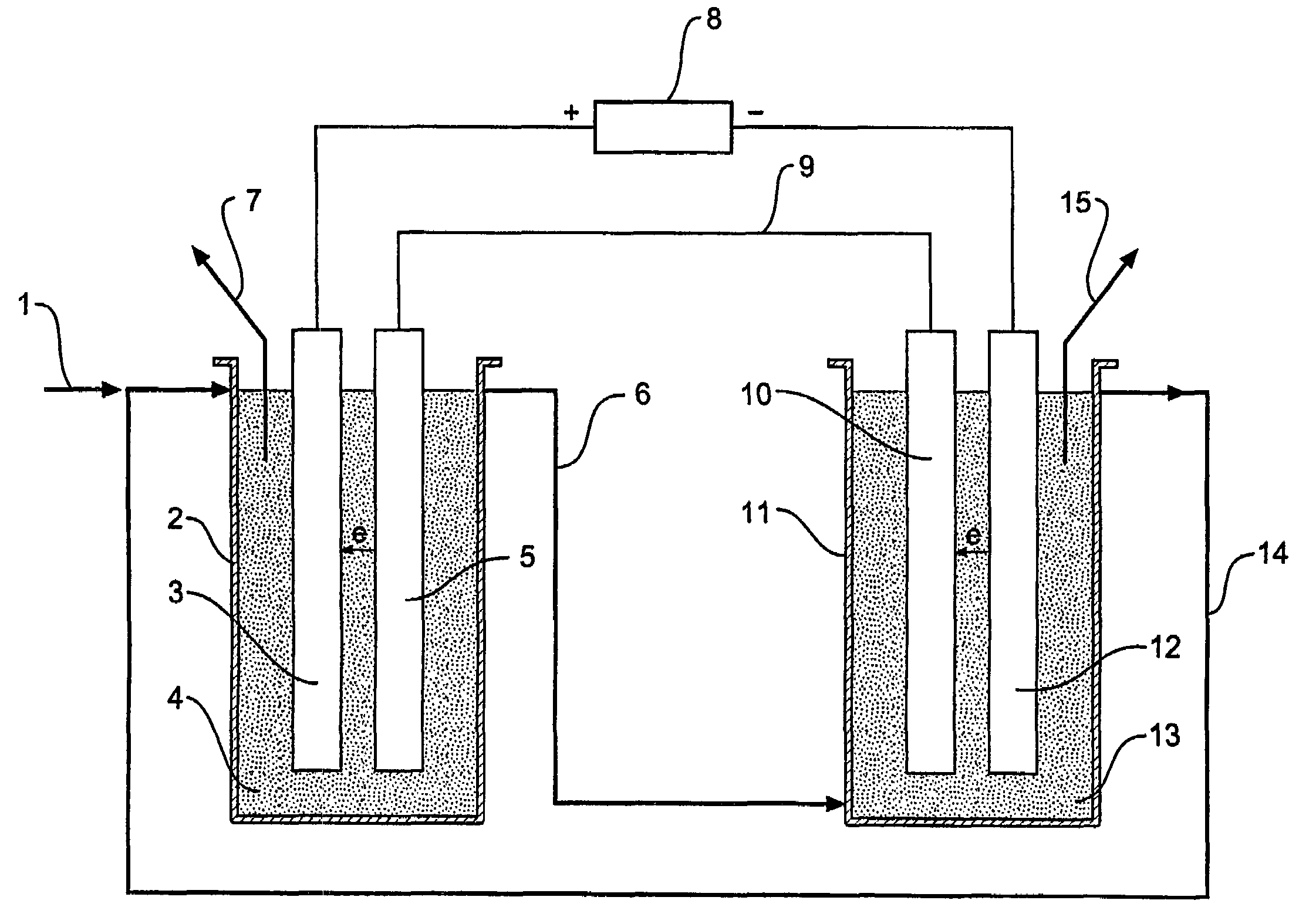
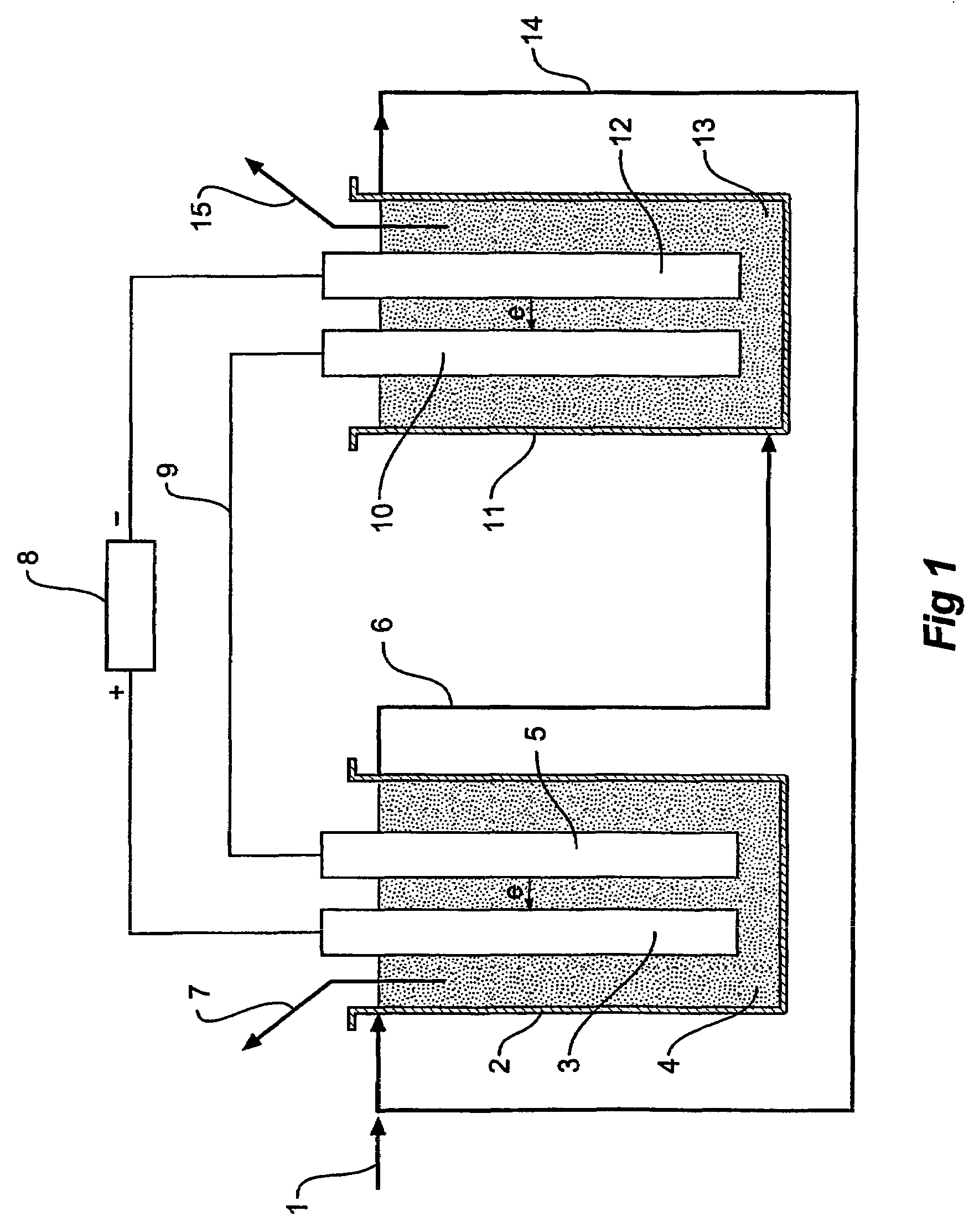
[0024]In one form therefore the invention is said to reside in n electrolytic process that converts solid, liquid, or gas hydrocarbon compounds and water to carbon dioxide and hydrogen at high reaction rates using an electrolytic cell that operates without a diaphragm at high pressure and moderate temperature using catalysts in an electrolyte, wherein the electrolytic cell consists of the anode cell containing an anode electrode connected to a DC power source and an anode solution electrode connected by an external conductor to a cathode solution electrode and a cathode cell containing a cathode electrode connected to the DC power source and the cathode solution electrode and an electrolyte containing the hydrocarbon compounds is reacted with water in the anode cell to produce carbon dioxide and hydrogen ions and the electrolyte containing the hydrogen ions is transferred to the cathode cell and hydrogen ions are reacted in the cathode cell to produce hydrogen.

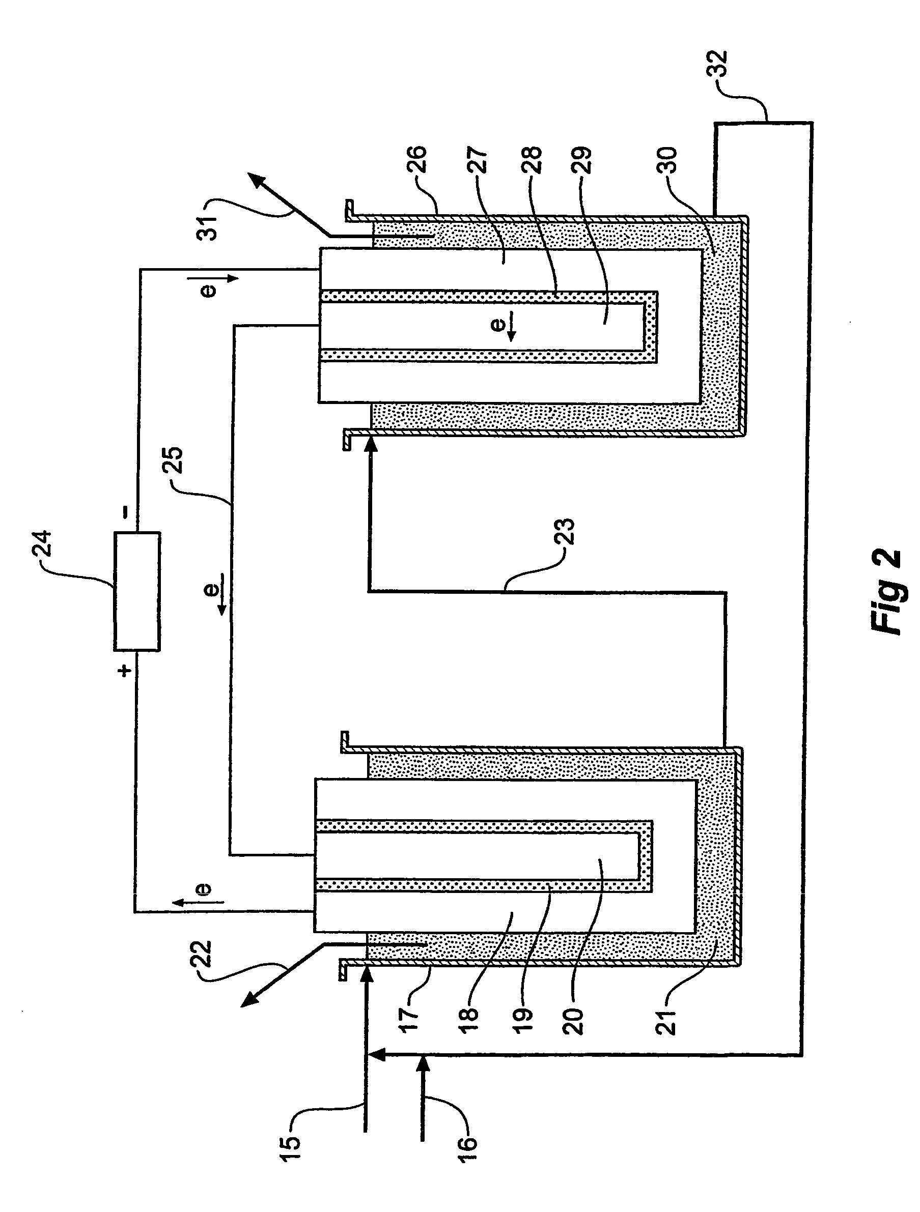
[0025]In an alternativ...


PUM

PropertyMeasurementUnit
temperatureaaaaaaaaaa
pressureaaaaaaaaaa
voltageaaaaaaaaaa

Abstract

This invention concerns the commercial production of electrolytic hydrogen from coal and other hydrocarbon compounds. The process provides high capacity and low impedance compared to conventional diaphragm electrolytic cells. The hydrogen produced is suitable for combined cycle gas turbines and fuel cell power generation plants and for proton electrolytic membrane fuel cell powered transport vehicles.

Description

FIELD OF INVENTION[0001]This invention concerns an electrolytic process for the commercial production of hydrogen from solid, liquid, or gas hydrocarbon compounds using a high capacity electrolytic cell as described in U.S. Pat. No. 5,882,502 Mar. 16, 1999 that functions without a diaphragm between the anode and the cathode. High capacity and low impedance of the electrolytic cell are necessary to achieve the high capacity required for the commercial production of hydrogen.INTRODUCTION[0002]Our way of life requires increasing energy in the form of electricity and transport energy. This must be achieved based on a reliable abundant energy source and with acceptable pollution of the environment, particularly the production of toxic and greenhouse gases.[0003]Coal is the most abundant and widely spread energy source of the world with reserves estimated to last for several hundred years. Table 1 shows the major production of coal and the portion used in electricity generation. At the pr...

Claims


Application Information

Patent Timeline
Patent Type & Authority Patents(United States)
IPC IPC(8): C25B1/02C25B1/00C25B15/00C25C1/00C25B9/00C25B9/16
CPCC25B1/02C25B15/00C25B9/16C25B9/00C25B9/40
Inventor GOMEZ, RODOLFO ANTONIO M
Owner RODOLFO ANTONIO M GOMEZ
Why Eureka
Try Eureka