

Organic light-emitting diode devices with improved operational stability
a light-emitting diode and organic technology, applied in the direction of discharge tube luminescnet screen, other domestic articles, natural mineral layered products, etc., can solve the problems of insufficient stability and persistent low operational stability, and achieve excellent luminance efficiency and color chromaticity, reduce drive voltage, and improve operational stability
- Summary
- Abstract
- Description
- Claims
- Application Information
AI Technical Summary
Benefits of technology
Problems solved by technology
Method used
Image

Examples
working examples 1 – 19
WORKING EXAMPLES 1–19
Electroluminescence of Aggregates of Various Materials
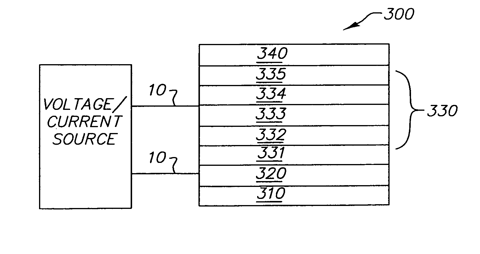
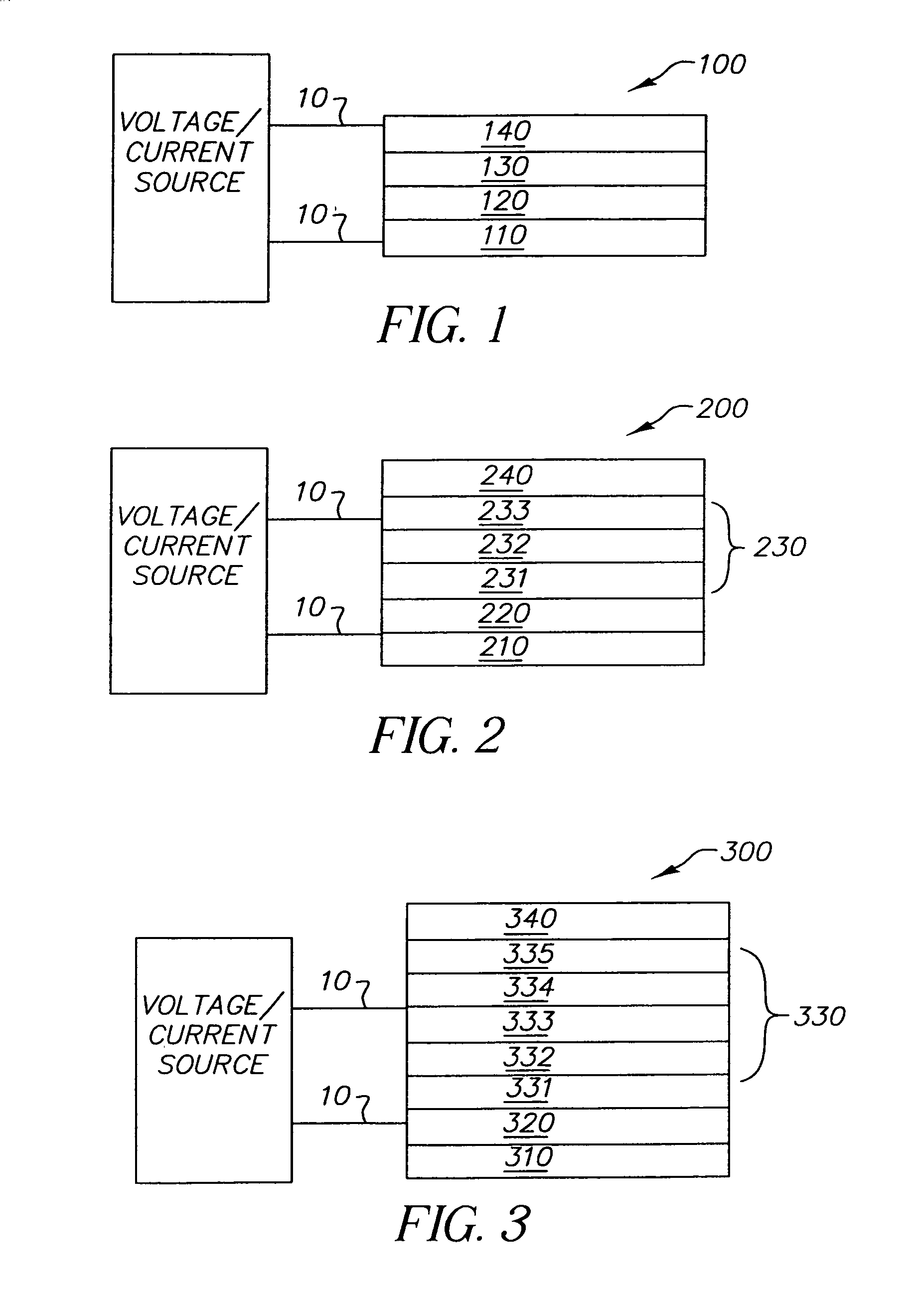
[1641]OLED devices were prepared as follows. A glass substrate coated with about 850 Å transparent indium-tin-oxide (ITO) conductive layer was cleaned and dried using a commercial glass scrubber tool. The ITO surface was subsequently treated with an oxidative plasma to condition the surface as an anode. Over the ITO was deposited a 10 Å thick hole-injecting layer of fluorocarbon (CFx) by plasma-assisted deposition of CHF3. The following layers were deposited in the following sequence by sublimation from heated crucible boats in a conventional vacuum deposition chamber under a vacuum of approximately 10−6 Torr: (1) a hole-transport layer, 750 Å thick, including NPB, (2) a luminescent layer, 350 Å thick, including the first and second host components in certain ratio (indicated in Table 1) and not containing luminescent dopants, (3) an electron-transport layer, 350 Å thick, including AlQ3, and (4) a cathode, ap...
working examples 21 – 25
WORKING EXAMPLES 21–25
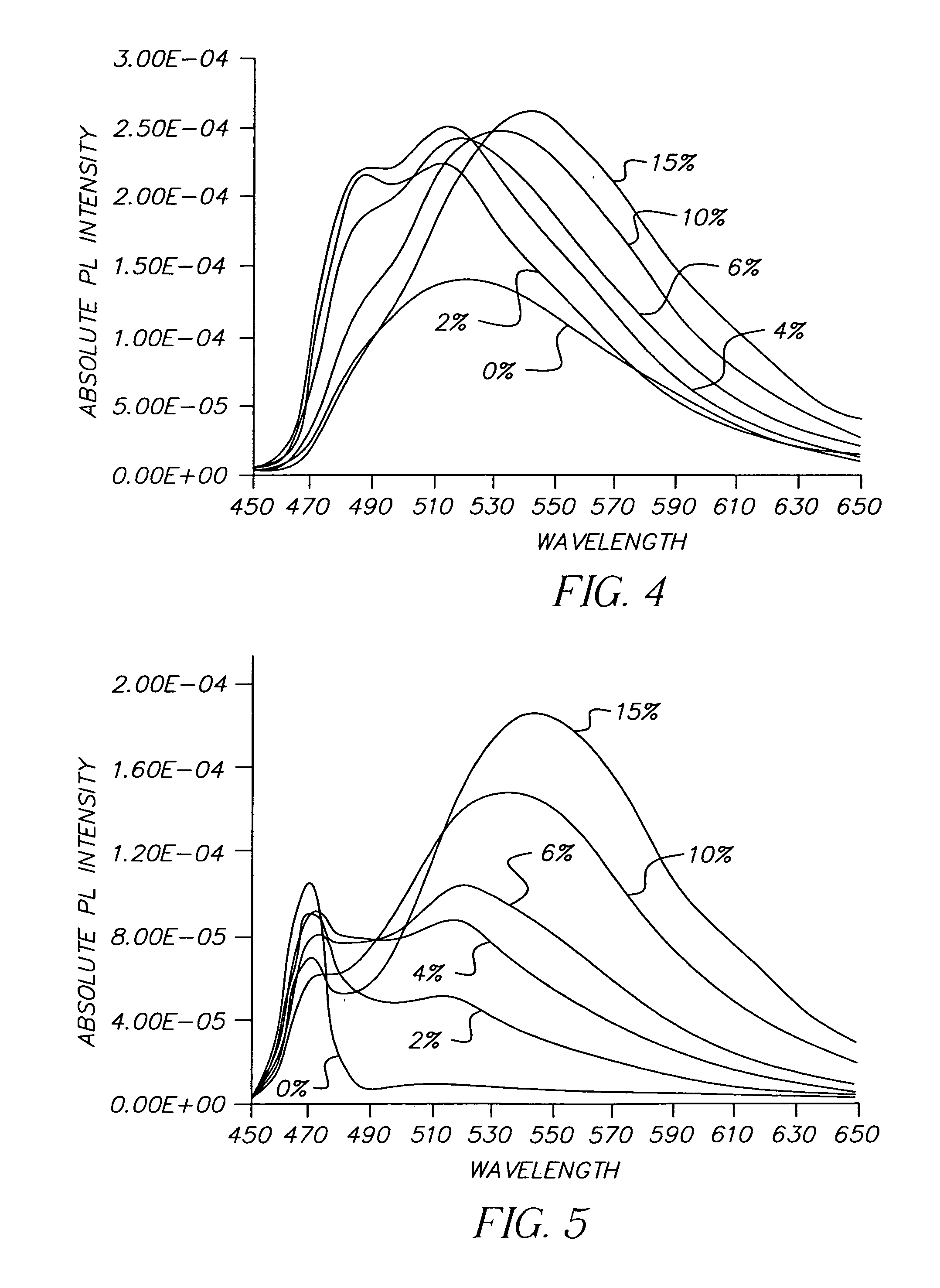
[1648]OLED devices 21–25 similar to the device of Comparative Example 20 were constructed, except that in the luminescent layer (2) naphtho[2,3-a]pyrene was used as the material for the first host component and AlQ3 as the material for the second host component. The relative amounts of naphtho[2,3-a]pyrene and AlQ3 on a volume basis were in the ratio 1:99, 2:98, 4:96, 10:90, and 15:85 for Examples 21, 22, 23, 24, and 25, respectively. The EL characteristics of the devices 21–25 are shown in Table 2. As can be seen from Table 2, devices 21–25 demonstrate as volume % of naphtho[2,3-a]pyrene increases:1) slight decrease in luminance efficiency followed by an increase; 2) shift of the emission color from green to green-yellow; 3) change in the Δ cd / A vs J behavior from gain to larger loss followed by a smaller loss; 4) from 300% to 1,000% improvement in lifetime relative to the Comparative Device 20.
working examples 27 – 29
WORKING EXAMPLES 27–29
[1650]OLED devices 27–29 similar to the device of Comparative Example 26 were constructed, except that in the luminescent layer (2) naphtho[2,3-a]pyrene was used as the material for the first host component and TBADN as the material for the second host component. The relative amounts of naphtho[2,3-a]pyrene and TBADN on a volume basis were in the ratio 2:98, 6:94, and 20:80 for Examples 27, 28, and 29, respectively. The EL characteristics of the devices 27–29 are shown in Table 2. As can be seen, devices 27–29 demonstrate as volume % of naphtho[2,3-a]pyrene increases:1) about 15% decrease in the drive voltage; 2) no change in luminance efficiency; 3) shift in color of emission from blue-green to yellow; 4) change in the Δ cd / A vs J behavior from loss first to larger loss and then to smaller loss; 5) from 550% to 1,700% improvement in lifetime relative to the Comparative Device 26.
PUM
| Property | Measurement | Unit |
|---|---|---|
| Percent by volume | aaaaa | aaaaa |
| Percent by volume | aaaaa | aaaaa |
| Percent by volume | aaaaa | aaaaa |
Abstract
Description
Claims
Application Information