Direct radio-frequency detection of nucleotide hybridization at microelectrodes

a radiofrequency detection and nucleotide technology, applied in the field of biosensors, can solve the problems of increasing the complexity and cost of detection techniques, limiting response time and sensitivity, and current can be difficult and unreliable, so as to achieve high-sensitivity detection of hybridization events and increase the mixing and modulation of high-frequency signals.

Active Publication Date: 2007-02-27
WISCONSIN ALUMNI RES FOUND
View PDF4 Cites 23 Cited by
  • Summary
  • Abstract
  • Description
  • Claims
  • Application Information

AI Technical Summary

Benefits of technology

[0005]In accordance with the invention, highly sensitive detection of hybridization events may be localized to a very small sensing region. Hybridized nucleotides in a cell sample alter an electrical double-layer having a nonlinear response to applied high frequency electromagnetic fields, resulting in increased mixing and modulation of a high frequency signal by a low frequency signal applied to the sample. The presence of modulation in the high frequency signal indicates that hybridization has occurred in the localized area to which the signal is applied. Detection of hybridization in this manner provides a nearly zero-background technique for sensing changes in the electrical double layer at microelectrode surfaces because of the absence of non-linearity in the bulk of the sample fluid in the cell.

Problems solved by technology

The use of such fluorescent tags or other labels increases the complexity and cost of the detection techniques.
It is desirable to miniaturize such detection systems to reduce costs and allow parallel processing, but as the physical size of the sensing region becomes smaller, employing current detection schemes which depend on measurements of changes in current can be difficult and unreliable, limiting the response time and sensitivity.

Method used


Image

  • Direct radio-frequency detection of nucleotide hybridization at microelectrodes
  • Direct radio-frequency detection of nucleotide hybridization at microelectrodes
  • Direct radio-frequency detection of nucleotide hybridization at microelectrodes

Examples


Embodiment Construction

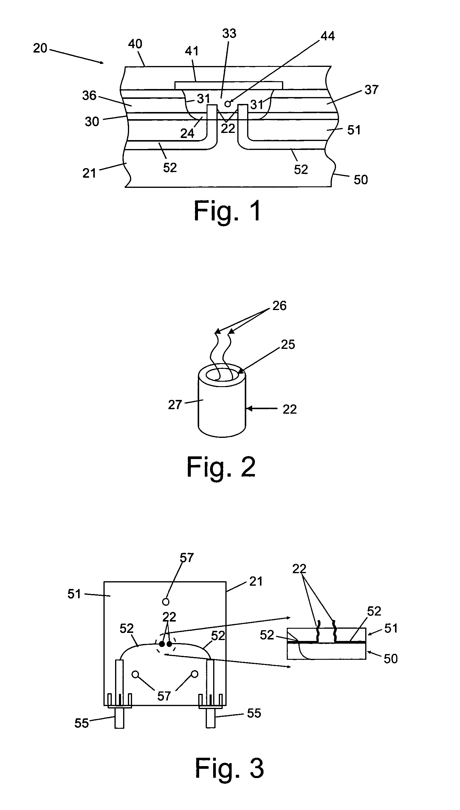
[0016]With reference to the drawings, an exemplary flow cell structure that may be utilized in a radio frequency detection apparatus is shown generally at 20 in FIG. 1 in cross-section. The flow cell 20 includes a base 21 with working electrodes 22 (two shown), mounted therein and extending above a top surface 24 of the base into a region in which a sample fluid may be held. As best illustrated in FIG. 2, the exposed portions of the working electrodes 22 include an exposed terminal surface 25 (e.g., having a gold coating, as discussed below) on which the nucleotide (illustratively shown at 26) may be immobilized. The central core conductor (e.g., of gold) which terminates on the surface 25 is preferably insulated from the surrounding sample by a layer of insulation 27 (e.g., polyimide)

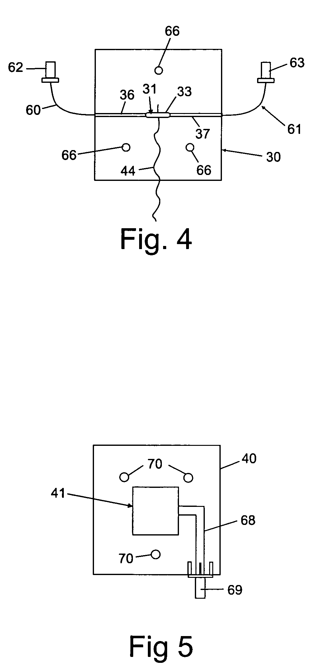
[0017]The flow cell 20 further includes an intermediate layer 30 which includes interior walls 31 defining the peripheral walls of a flow cell chamber 33, an inlet channel 36 extending from an inlet en...


PUM

PropertyMeasurementUnit
frequencyaaaaaaaaaa
frequencyaaaaaaaaaa
areaaaaaaaaaaa

Abstract

Radio-frequency (RF) excitation is used for direct detection of hybridization events at microelectrodes with surface-attached DNA oligomers. A homodyne reflectometer operates on a high frequency carrier to detect the presence of a low-frequency modulation signal. Without non-linearities in an interface, the modulation signal is not impressed upon the carrier signal. As such, the reflectometer can sensitively measure changes in dielectric properties without interference from other sources of capacitance/resistance unrelated to the reaction at the surface.

Description

CROSS-REFERENCE TO RELATED APPLICATIONS[0001]The present application claims priority to U.S. Provisional App. No. 60 / 422,907 filed on Nov. 1, 2002, which is incorporated herein by reference.REFERENCE TO GOVERNMENT RIGHTS[0002]This invention was made with United States government support awarded by the following agencies: ONR N00014-01-1-0654. The United States government has certain rights in this invention.FIELD OF THE INVENTION[0003]This invention pertains generally to the field of biosensors and particularly to sensors for the detection of hybridization events.BACKGROUND OF THE INVENTION[0004]The use of biologically modified surfaces as active sensing regions for detection, identification, and sequencing of biological molecules is being intensively studied. In most sensors, selectivity is achieved by binding a known probe to the surface. The binding of the target molecules in the sample to the probe is detected by the generation of some physical or chemical signal. Several differ...

Claims


Application Information

Patent Timeline
Patent Type & Authority Patents(United States)
IPC IPC(8): C12Q1/68C07H21/02C07H21/04C12M1/00B01L3/00C40B40/06C40B70/00G01N27/22
CPCB82Y15/00B82Y30/00G01N27/221C12Q1/6825B01J2219/00565B01J2219/00653B01J2219/00704B01J2219/00722B01L3/5027C40B40/06C40B70/00C12Q2565/607
Inventor VAN DER WEIDE, DANIEL W.HAMERS, ROBERT J.PECK, JOHN R.CAI, WEI
Owner WISCONSIN ALUMNI RES FOUND
Why Eureka
Try Eureka