[0065]It is an
advantage of the invention that
layers or other zones, e.g., partial
layers such as precut inserts, can have void conditions differing in adjacent zones. By void condition is meant the percentage of the sheet represented by voids, which are generally found in the form of of plastic or
metal to aid in sealing and for other useful properties. By properly utilizing suitable interlayers with impregnated materials, an external binder can be eliminated, further decreasing electrical and
thermal resistance.
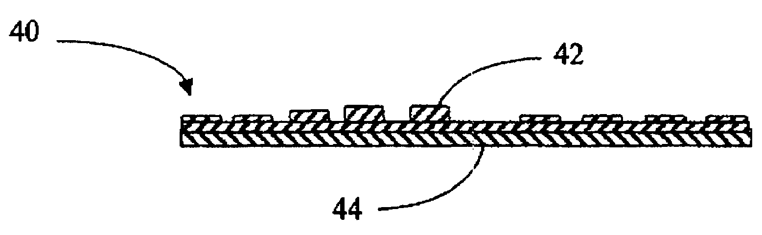
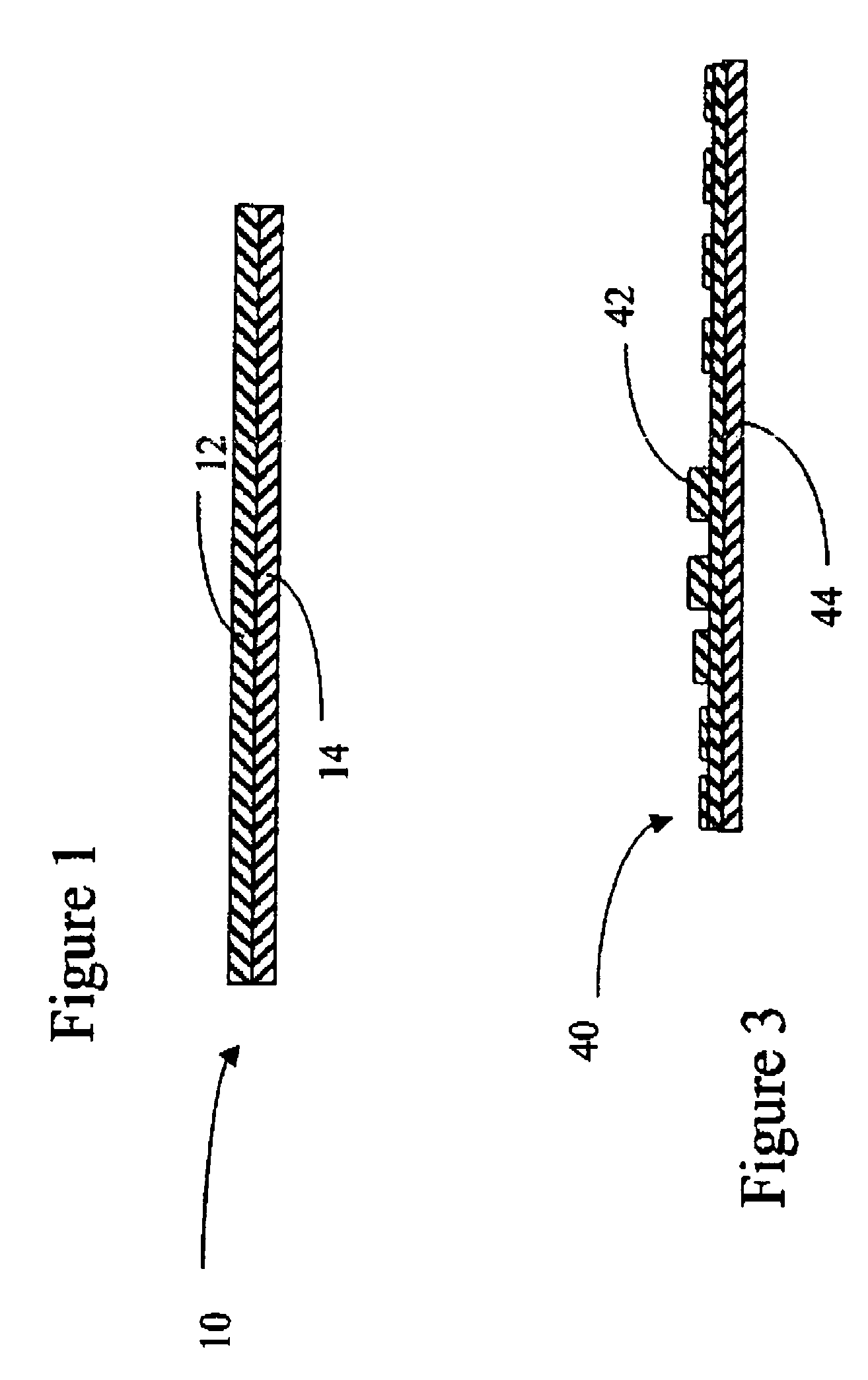
[0066]Referring again to FIG. 1, a
composite material 10 of the invention, is shown schematically, and is of type useful for a number of purposes including as a substrates for forming embossed flexible graphite articles. The composite is made of a plurality of
layers, here two layers, 12 and 14. However, the number of layers is not limited to two, and up to ten or more layers can be employed to
advantage. Indeed, an important aspect of the invention is the opportunity to improve the product through the reduction of variation in area weight. When randomly selected the variation in a laminate will be reduced by the square root of the number of layers in the laminate, through deliberate selection, further improvements can be achieved. Impregnated and dried materials in a condition for embossing may be assembled to accumulate any desired target density. When then formed the assembled pieces will combine as one. With suitable selection in density for the layers of a laminate, the
assembly will yield a more true representation of the die cavity and show fewer discontinuities resulting from shear during forming than would a single layer. For example, nine layers of 8-mg / cm2 may be formed into a single 72-mg / cm2 molding blank.
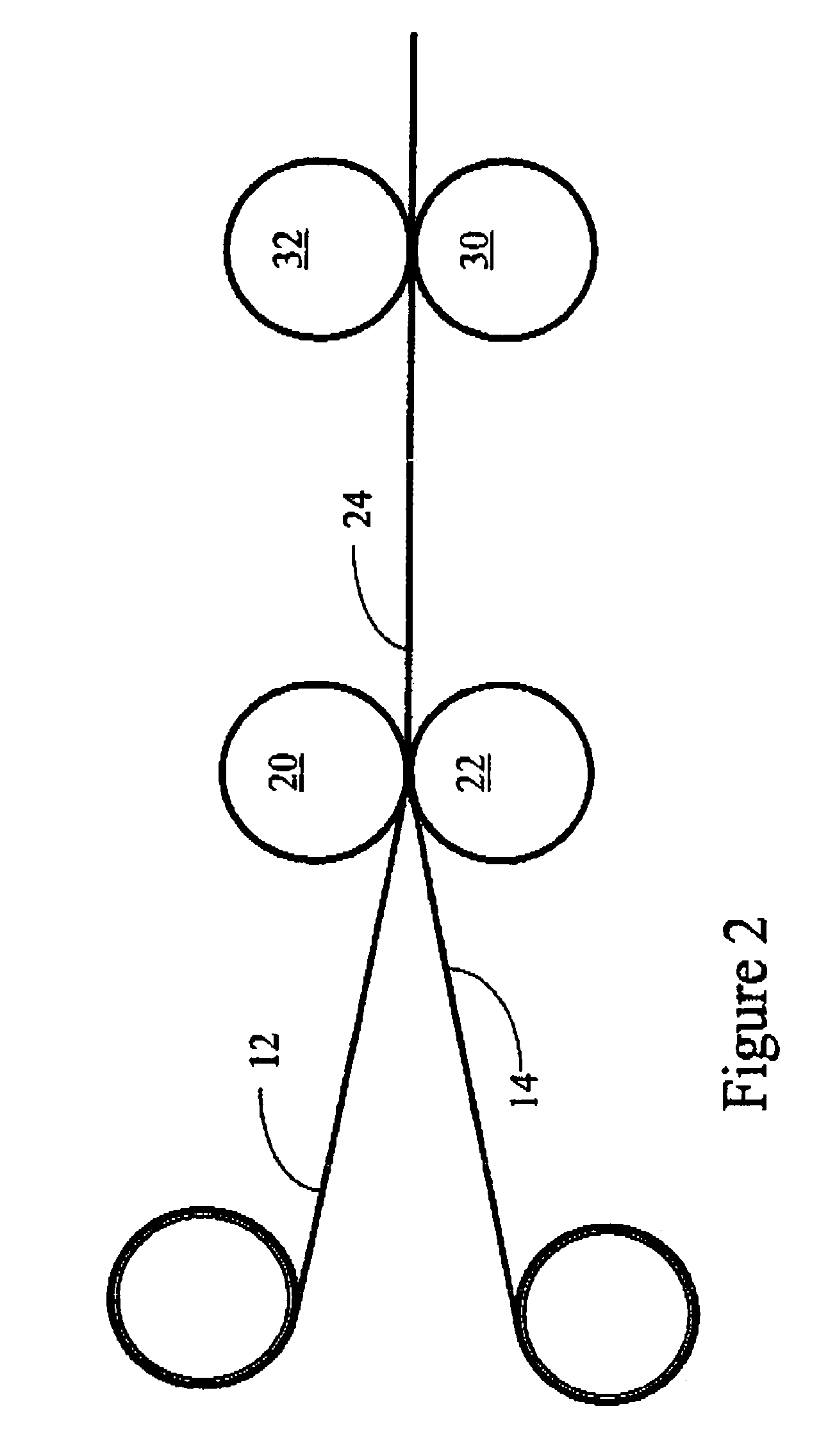
[0067]A material of the type shown in FIG. 1 can be formed continuously from rolled sheets of resin-impregnated flexible graphite foil or by hand lay-up. In one automated process, as illustrated in FIG. 2, two sheets, 12 and 14 are brought together with
contact pressure sufficient to promote substantial interfacial sheet contact by pressing between rollers 20 and 22. The resulting composite 24 can be distributed in this form as a roll or
cut sheet. If desired, the composite 24 can be pressed under sufficient pressure and heat, with or without the addition of additional binder or a
solvent for the binder already present.
[0068]In some cases, it will prove advantageous to use the lowest density layers of the laminate where the embossing detail is most critical and very
high density where the surface is to be continuous. Appropriate interlayers of suitable materials, such as nonreactive
sheet material, preferably perforated or expanded, or insert mesh fabric can provide improved
toughness, or entrapped air. Generally, this is accomplished by the application of pressure to the sheet (which also has the effect of densifying the sheet) so as to reduce the level of voids in the sheet, for instance in a calendar mill or platen press. Advantageously, the flexible graphite sheet is densified to a density of at least about 1.3 g / cc (although the presence of resin in the
system can be used to reduce the voids without requiring densification to so high a level).Preparation of Composite
Graphite Materials
[0069]The invention provides a material useful as a substrate for an embossed flexible graphite sheet and comprises a composite flexible graphite sheet comprising a plurality of zones (e.g., layers or partial layers) of resin-impregnated, flexible graphite sheet. At least one of the plurality of zones has a characteristic different than at least one other of said plurality of zones. Among the various characteristics that are advantageously varied between zones according to the invention are all of those above or as may otherwise be measured and can be related to properties of a final shaped article or an effect on the process for making it. Typically, the invention can provide useful properties in the characteristics of final shaped articles when the difference in the characteristics referred to is greater than about 5%, and more typically from about 10% up to about 200%, based on the smaller of the two values. In many cases, differences of from about 20 to about 75% on this basis are valuable. In others difference values up to as much as 500% can have a particular utility.
[0070]In one form, the
composite material of the invention will be provided with a unique combination of properties by further including a layer of a diverse material interposed between at least two layers of said plurality of layers. The diverse material can be a foraminous material, e.g., selected for any of a variety of added advantages and is typically one selected from the group consisting of perforated films and foils, and woven and nonwoven fabrics and webs of plastic,
metal and / or natural composition. In all cases, the materials are employed to provide a unique ability to control final shaped article characteristics, e.g., density and surface properties, by preselecting layers of different characteristic, e.g., density or void condition, to comprise the layers of the composite. In other cases, the diverse material can be a nonporous film, sheet or foil
conductivity and thus add value to the laminate. Such materials, preferably foraminous in structure, can add useful properties to the final product and the material of the invention as well. These materials can add strength and / or enhance any of the above-noted characteristics for desired end uses. A nonporous sheet, foil or film can be employed for a useful purpose such as sealing or the like where it does not interfere with the end use.

