
Low thermal mass fluorometer
a fluorometer and low thermal mass technology, applied in the field of low thermal mass fluorometers, can solve the problems of large and expensive system, limited budget, and limited space, and achieve the effects of improving thermal control, low cost, and adding spectral bandwidth
- Summary
- Abstract
- Description
- Claims
- Application Information
AI Technical Summary
Benefits of technology
Problems solved by technology
Method used
Image

Examples
Embodiment Construction
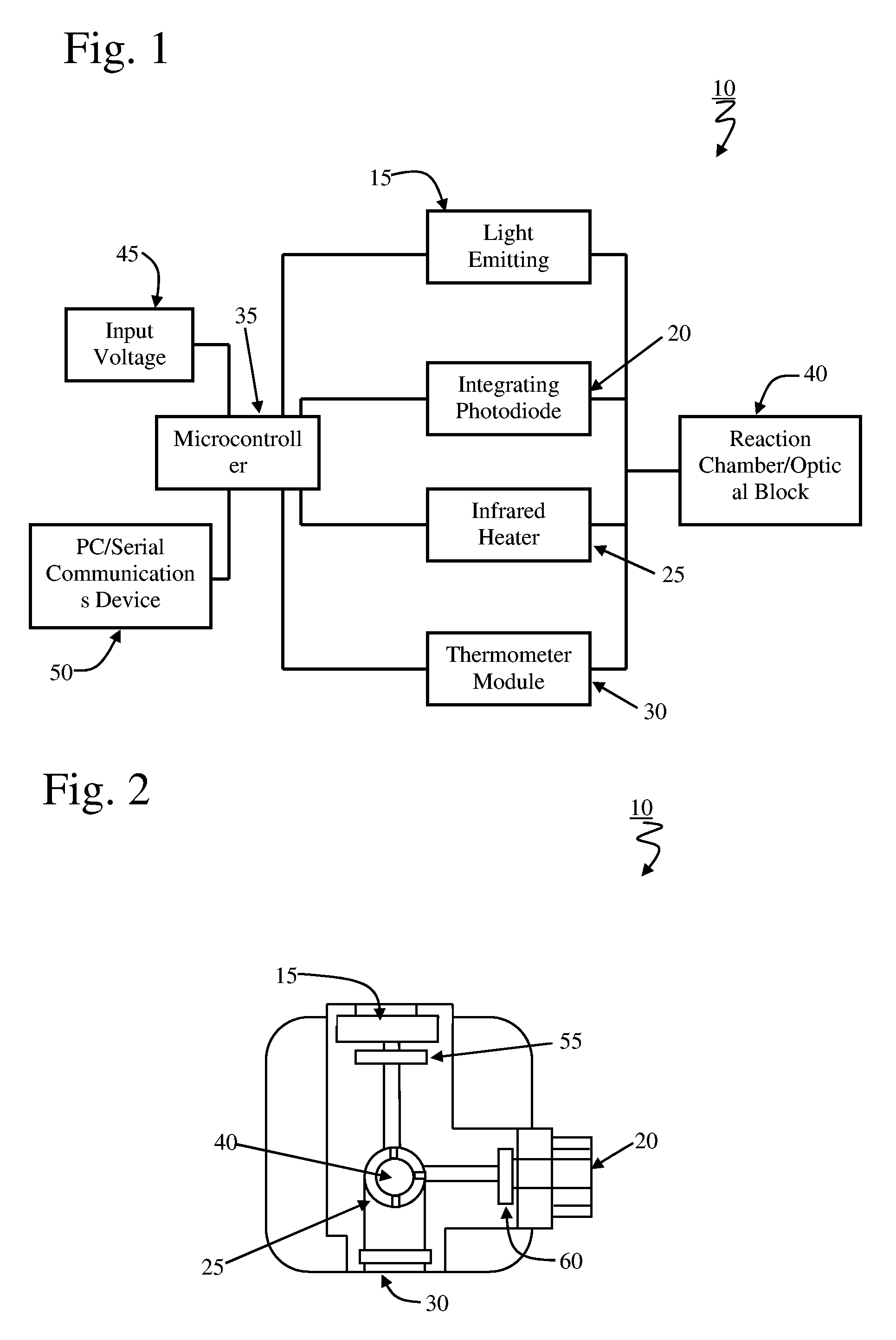
[0018]With reference to FIG. 1, in a particular embodiment the low thermal mass fluorometer 10 in accordance with the present invention incorporates a simple light emitting diode (LED) light source 15, and an integrating photodetector 20 for fluorometry. A MEMS-based infrared radiant heater 25 and an infrared thermometer module 30 make up the thermal regulation system. All of these components are controlled with custom software communicated through a microcontroller 35. In typical operation, the sample to be evaluated is placed in the reaction chamber 40. Power is supplied 45 either externally or through an integrated power supply and a serial communication interface 50 is used to provide a display for data output and a means to control the temperature cycling and optical parameters.
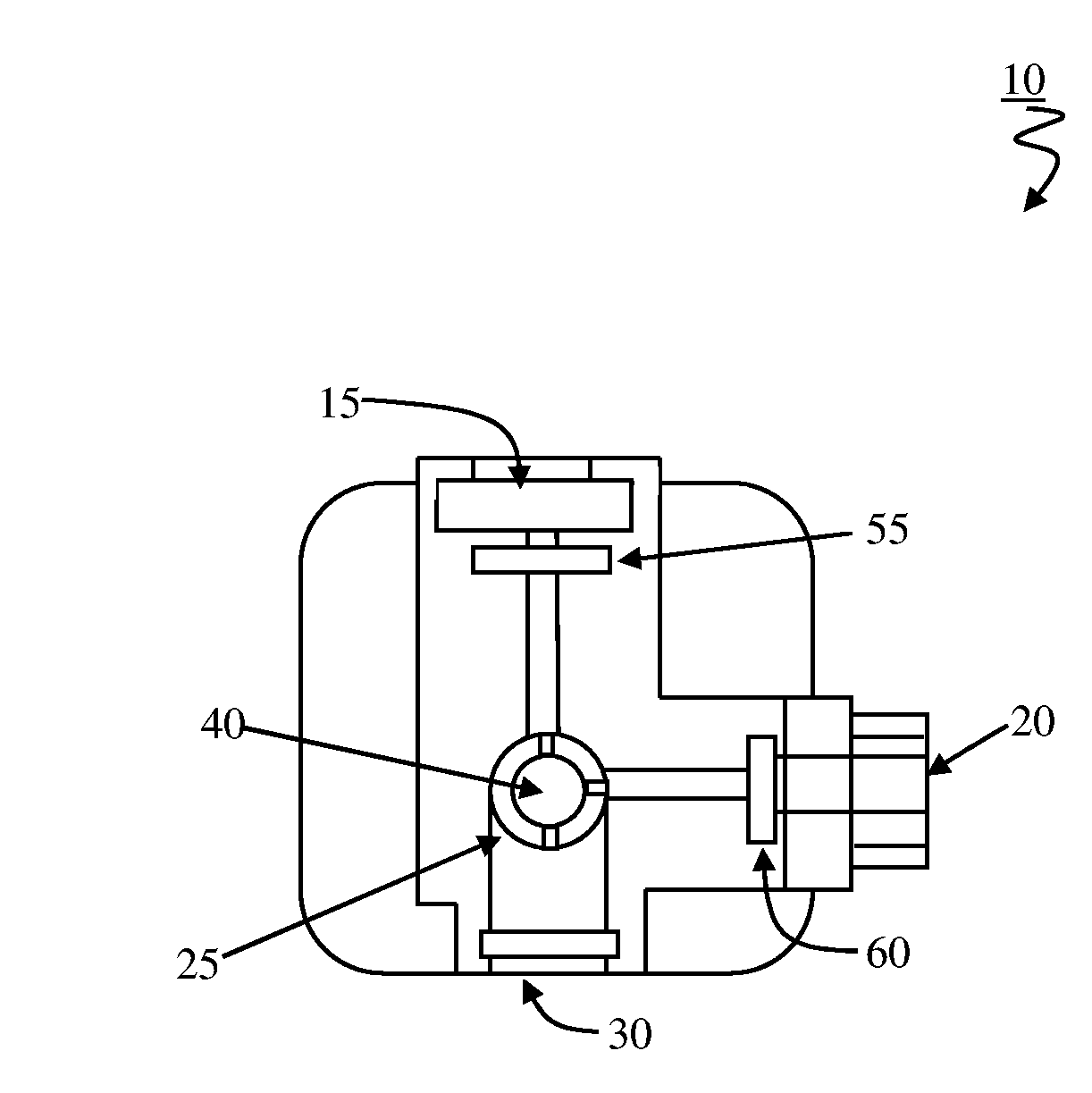
[0019]FIG. 2 illustrates the relative positioning of the elements of the low thermal mass fluorometer in accordance with the present invention. As shown the light emitting diode 15 and the photodetector ...
PUM
| Property | Measurement | Unit |
|---|---|---|
| dark currents | aaaaa | aaaaa |
| response time | aaaaa | aaaaa |
| temperatures | aaaaa | aaaaa |
Abstract
Description
Claims
Application Information