Monolithic semiconductor light source with spectral controllability
a semiconductor light source and monolithic technology, applied in the field of optical systems, can solve the problems of large nonlinear effects, low input to amplifiers, and low signal-to-noise ratio degradation, and achieve the effects of high power, and raman amplification of optical signals within fibers
- Summary
- Abstract
- Description
- Claims
- Application Information
AI Technical Summary
Benefits of technology
Problems solved by technology
Method used
Image
Examples
first embodiment
6.2.2.1 First Embodiment
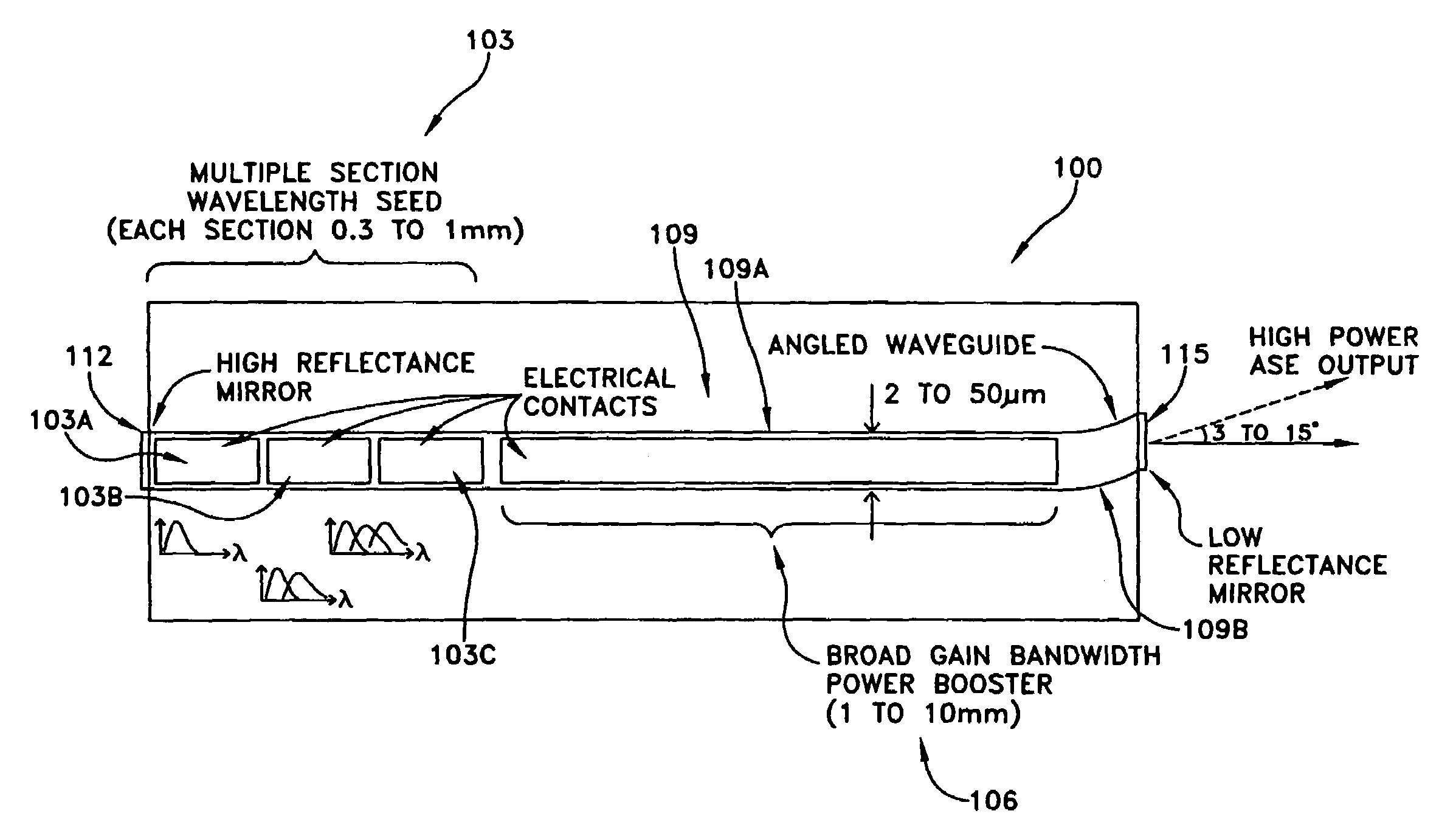
[0088]FIG. 10 is a schematic diagram of a semiconductor die 100 used in a first preferred embodiment. The die 100 consists of a serial connection of a wavelength seed section 103 and a power booster or power amplification section 106 formed along a semiconductor waveguide 109.
[0089]The wavelength seed section 103 preferably comprises multiple subsections 103A, 103B, 103C, etc. formed along the semiconductor waveguide 109. Three subsections 103A, 103B, 103C are shown in FIG. 10; however, it should be appreciated that this number is merely exemplary and more or less than this number of wavelength seed subsections may be used. The gain profile within each subsection 103A, 103B, 103C, etc. is chosen so as to provide ASE in a particular wavelength range. The gain profiles can be defined in each subsection 103A, 103B, 103C, etc. by such techniques as epitaxial regrowth or quantum well intermixing. The quantum well blocks of these subsections are designed to provide...
second embodiment
6.2.2.2 Second Embodiment
[0095]FIG. 11 is a schematic diagram of a semiconductor chip 200 and optical train 203 used in a second preferred embodiment. Although multiple chips can be used, this embodiment will be described in the context of a single chip 200 comprising an array of parallel waveguides 206, where the array comprises a plurality (e.g., 2 to 10) of parallel waveguides 206A, 206B, 206C, etc. The gain profile (i.e., peak wavelength and shape) of each waveguide 206A, 206B, 206C, etc. is chosen so as to provide the ASE output in a particular wavelength range (e.g., 3–30 nm).
[0096]The gain profiles can be defined within each waveguide 206A, 206B, 206C, etc. by employing such techniques as epitaxial regrowth, quantum well intermixing or other techniques known in the art. The spectral width and intensity of the ASE emitted from each waveguide 206A, 206B, 206C, etc. can be tailored through the design of the active region, the length of the waveguide, and active adjustment of the...
third embodiment
6.2.2.3 Third Embodiment
[0100]FIG. 12 is a schematic diagram of a semiconductor chip 300 and optical train 303 used in a third preferred embodiment. The die 306 consists of a wavelength seed section 309 which is power multiplexed by a multiplexer 312 into a long low loss power amplification (or booster) waveguide 315. Wavelength seed section 309 preferably comprises a plurality of wavelength seeds 309A, 309B, 309C, etc. Both the seed light waveguides 309A, 309B, 309C, etc. and the power booster waveguide 315 are designed for broadband ASE emission, just as in the first embodiment (FIG. 10) discussed above. A high reflectance mirror is provided for each of the seed waveguides 309A, 309B, 309C, etc. These mirrors may be independent of one another, or they may be different sections of a single mirror, such as is shown in FIG. 12 with the high reflectance mirror 318. The reflectivity profiles of the high reflectance mirror for each seed waveguide 309A, 309B, 309C, etc. are optimized to ...
PUM
 Abstract
Description
Claims
Application Information
 - R&D
- Intellectual Property
- Life Sciences
- Materials
- Tech Scout
- Unparalleled Data Quality
- Higher Quality Content
- 60% Fewer Hallucinations
Browse by: Latest US Patents, China's latest patents, Technical Efficacy Thesaurus, Application Domain, Technology Topic, Popular Technical Reports.
© 2025 PatSnap. All rights reserved.Legal|Privacy policy|Modern Slavery Act Transparency Statement|Sitemap|About US| Contact US: help@patsnap.com


