Method and plate apparatus for dew point evaporative cooler

a technology of evaporative cooler and plate apparatus, which is applied in the field of evaporative fluid conditioning, can solve the problems of insufficient availability of residential or after market evaporative cooler, inconvenient use, and inconvenient use, and achieve the effect of small pressure drop

Inactive Publication Date: 2007-04-03
F F SEELEY NOMINEES
View PDF15 Cites 63 Cited by
  • Summary
  • Abstract
  • Description
  • Claims
  • Application Information

AI Technical Summary

Benefits of technology

[0026]It is yet another object of the invention to provide an efficient indirect evaporative cooler, allowing cooling of a stream of a product to substantially the working gas ...

Problems solved by technology

However, indirect evaporative cooling is as yet only used in specially built commercial applications, and is not yet available on the market as a residential or after market product.
This is due to certain disadvantages of known indirect evaporative coolers and methods: excessive cost, ineffective thermodynamic cycle that does not allow for enough cooling of air for the expenses involved, ineffective water supply system, scale buildup, poor or expensive heat exchanger, excessive pressure drop, difficulty approaching the dew point of the air stream (the theoretical limit of cooling), relatively high dew points in humid atmospheres, large pressure drops across the heat exchange apparatus, large heat exchange apparatus, and in some designs, reliance on a good deal of ancillary equipment.
U.S. Pat. No. 4,002,040 issued to Munters et al on Jan. 11, 1977 discloses a heat exchanger in which there is no mixing between canal...

Method used


Image

  • Method and plate apparatus for dew point evaporative cooler
  • Method and plate apparatus for dew point evaporative cooler
  • Method and plate apparatus for dew point evaporative cooler

Examples


second embodiment

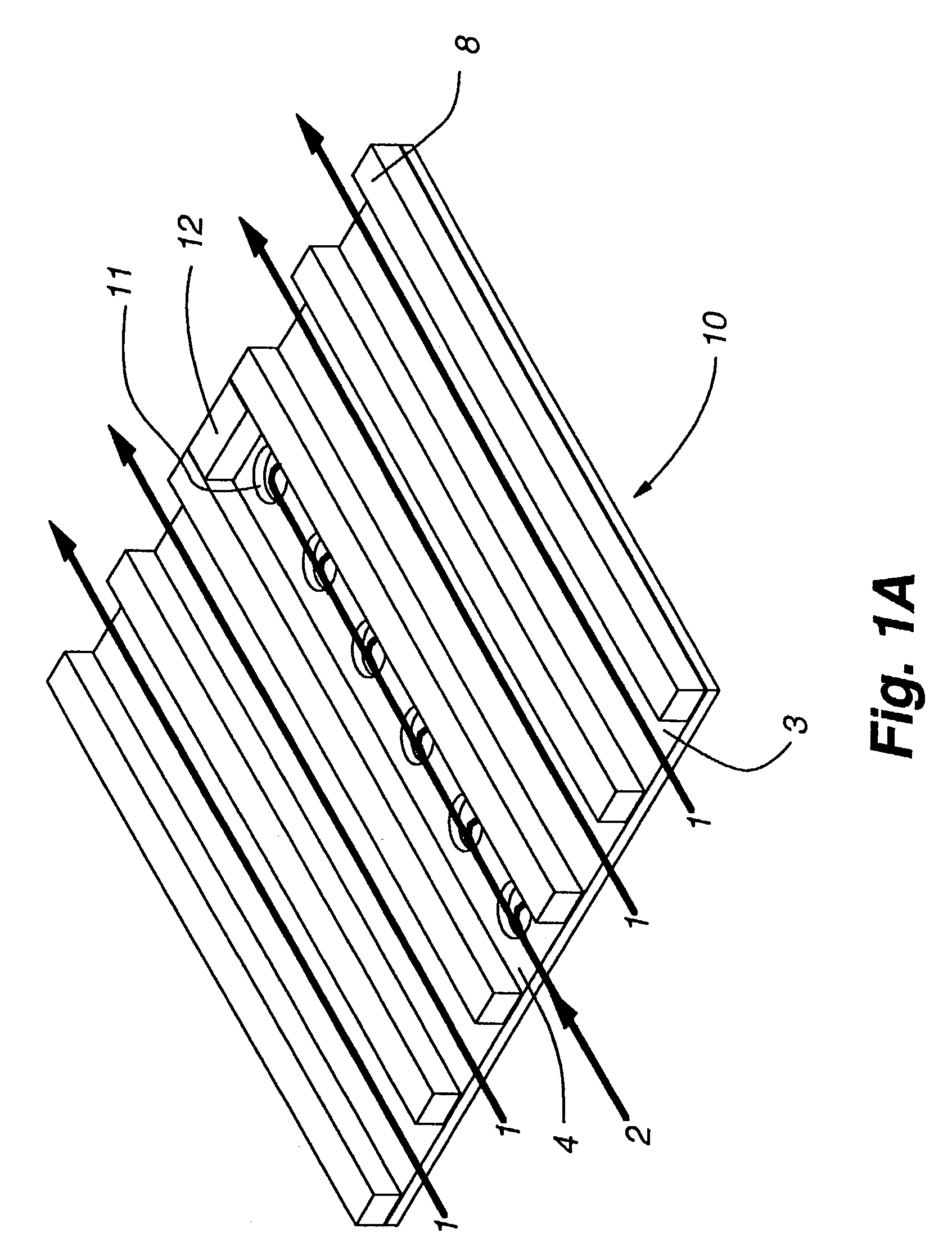
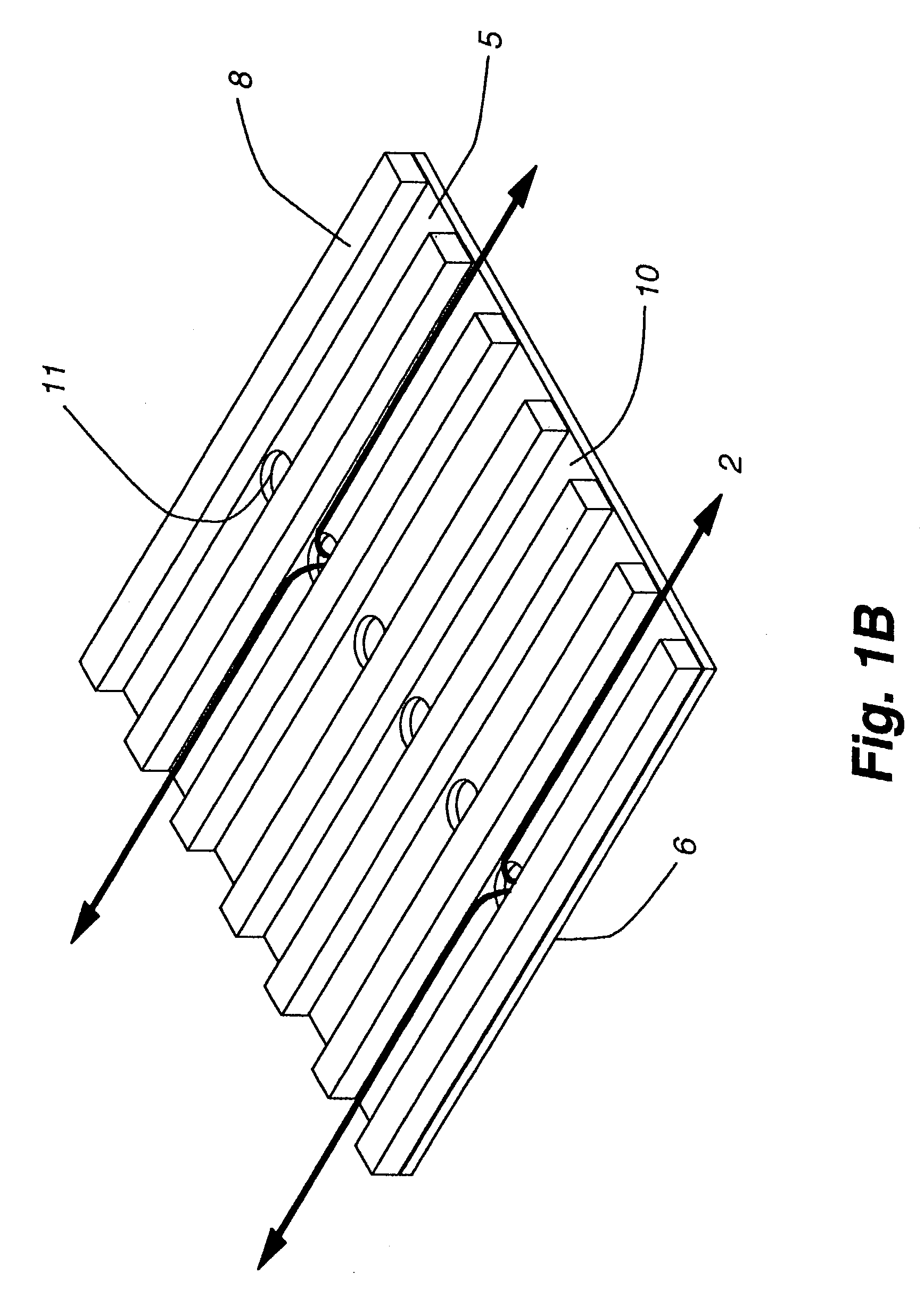
[0064]FIG. 1a is a three dimensional perspective and schematic representation of the element of the invention. In this embodiment, plate 6 has perforations 11 along one side rather than down the middle, as in the previous embodiment. Channel guides 8 create channels 3 and 4. In this embodiment, channel guides 8 are ribs, but they may be other types of guides, as previously discussed. Channel guide 8 also serves to prevent flow of gases off of one edge of plate 6. Working gas stream 2 flows in channel 4, product stream 1 flows in channel 3. Gas stream 2, the working gas, flows through perforations 11 to channel 5 (not visible), and then flows across the obverse side of plate 6 to depart plate 6 as gas stream 2.

third embodiment

[0065]FIG. 2 is a three dimensional perspective and schematic representation of the invention, showing the gas flow path when the invention is used to warm and humidify an air stream with water. Thus, in this embodiment and those following, the gas steams may be referred to as air streams, and the cooling liquid will be assumed to be water. In winter months, it is advantageous to exchange heat between exhaust air leaving a warmed space and cold fresh air being brought in from the atmosphere, i.e. the out door air or other source of environmental air. This reduces the heat required to warm the fresh air. The present invention also allows the addition of humidity to the fresh air, thus addressing another winter problem: cold outside air that has condensed moisture out and therefore has a low absolute humidity or extremely dry air that results in dry inside air as the moisture on the inside reduces with fresh air changes with the outside. The “cycle selection” as to which stream of air...

fifth embodiment

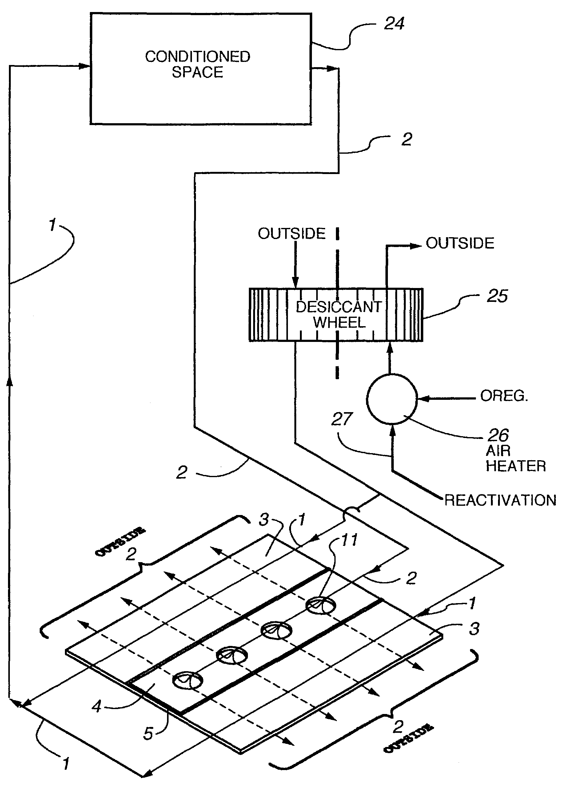
[0071]FIG. 4 is a partially three dimensional perspective and schematic representation of the flow path of the invention showing the gas flow when the invention is used with recirculating gas steams, and further showing the gas flow in the context of use. In this embodiment of the invention, air from a conditioned space is cooled again and returned as the product fluid. This results in a saving of energy and additional cooling of the product air stream.

[0072]Plate 6 has channel guides, channels, and a plurality of perforations collectively numbered 11. Air stream 1 emerges from desiccant wheel 25 before passing over the dry side of plate 6 in channels, where it transfers heat to plate 6 by conduction. Air stream 1 is then passed to conditioned space 24 and eventually recirculated to desiccant wheel 25.

[0073]Channel guides segregate working air stream 2 from product air stream 1 after desiccant wheel 25. It passes through channel, where it rejects heat to plate 6 and flows through pe...


PUM


Abstract

An improved method and apparatus for indirect evaporative cooling of a fluid stream to substantially its dew point temperature. Plate heat exchanger has perforations 11 and channels 3, 4 and 5 for gas or a low temperature for liquids on a dry side and wet side. Fluid streams 1 flow across the dry side 9, transferring heat to the plate. Gas stream 2 flows across the dry side and through perforations to channels 5 on wet side 10, which it then cools by evaporative cooling as well as conductive and radiative transfer of heat from plate. A wicking material provides wetting of wet side. In other embodiments, a desiccant wheel may be used to dehumidify the gas, air streams may be recirculated, feeder wicks 13 and a pump may be used to bring water from a water reservoir, and fans may be used to either force or induce a draft. The wicking material may be cellulose, organic fibers, organic based fibers, polyester, polypropylene, carbon-based fibers, silicon based fibers, fiberglass, or combinations of them. The device may be operated in winter months to scavenge heat from exhaust gases of a space and thus pre-heat fresh air, while simultaneously humidifying the fresh air.

Description

[0001]This application is a continuation-in-part of U.S. Pat. No. 6,581,402 Issued Jun. 24, 2003, entitled “METHOD AND PLATE APPARATUS FOR DEW POINT EVAPORATIVE COOLER”, which claims the benefit of U.S. Provisional Patent Application Ser. No. 60 / 236,047, filed Sep. 27, 2000, entitled “IMPROVED METHOD AND MEMBRANE APPARATUS FOR DEW POINT EVAPORATIVE COOLER”, inventors, Valeriy Maisotsenko, et al.BACKGROUND OF THE INVENTION[0002]1. Field of the Invention:[0003]The invention relates to the field of evaporative fluid conditioning. More specifically, the invention relates to the field of sensible cooling of fluids (gas, liquid or mixtures with and without phase changes) to substantially the dew point for gas by indirect evaporative cooling within a heat exchanger having canalized gas and fluid flows and a lateral temperature gradient across the heat exchange plates.[0004]2. Description of the Prior Art[0005]Indirect evaporative cooling is a method of cooling a gas stream, usually air, by...

Claims


Application Information

Patent Timeline
IPC IPC(8): F28C1/00F02M23/14F28F3/00F24F1/0071F24F3/14F24F5/00F28D5/02
CPCF24F3/1411F24F3/1423F24F5/0035F28D5/02F24F2001/0092F24F2003/144F24F2203/1036F24F2203/1056F24F2203/1068F24F2203/1084Y02B30/545F24F1/0007Y02B30/54F24F1/0071
Inventor MAISOTSENKO, VALERIYGILLAN, LELAND E.HEATON, TIMOTHY L.GILLAN, ALAN D.
Owner F F SEELEY NOMINEES
Why Eureka
Try Eureka