
Video cassette recorder and RCC type switching power supply

a video cassette recorder and power supply technology, applied in the field of rcc (ringing choke converter) type switching power supply, can solve the problems of increasing the cost of parts, poor total temperature characteristic, and high cost of shunt regulators as ics, and achieves the effect of suppressing the number of transistors used in error detection circuits, good temperature characteristic, and increasing the number of zener diodes

Inactive Publication Date: 2007-04-03
FUNAI ELECTRIC CO LTD
View PDF6 Cites 13 Cited by
  • Summary
  • Abstract
  • Description
  • Claims
  • Application Information

AI Technical Summary

Benefits of technology

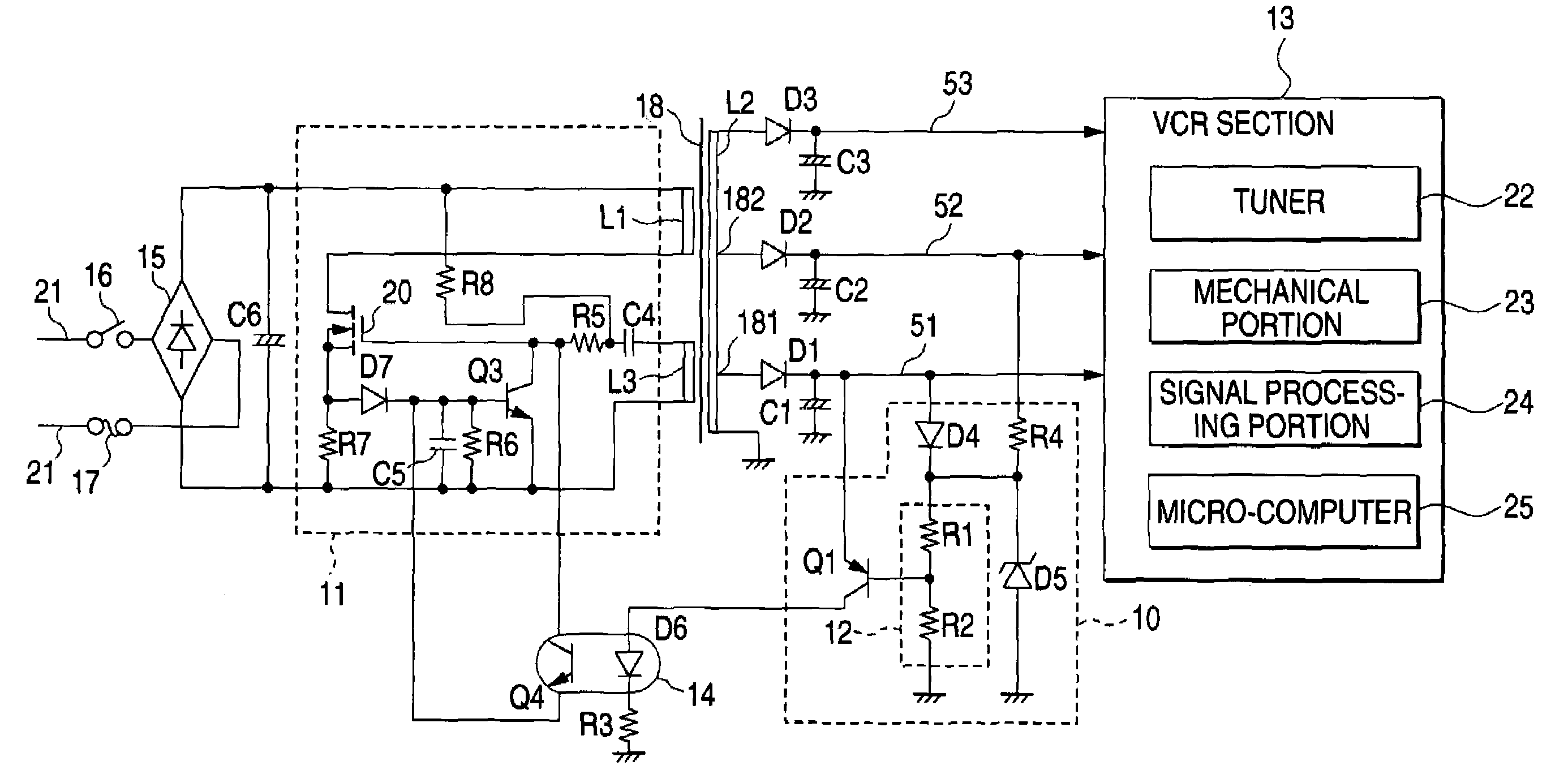
[0007]It is therefore an object of the invention is to provide a video cassette recorder equipped with an RCC type switching power supply in which increase in the number of transistors used in an error detection circuit can be suppressed even in the case where a voltage of 5 V is stabilized with good temperature characteristic and in which increase in the number of Zener diodes can be prevented even in the case where a fuse is provided on the primary side so that the fuse can be broken well when abnormal voltage increase occurs in the secondary side.
[0008]Another object of the invention is to provide an RCC type switching power supply in which a Zener diode that functions as a load on the secondary side to break a fuse on the primary side when abnormal increase occurs in an output voltage on the secondary side is provided so as to serve also as a Zener diode for generating a reference voltage so that increase in the number of Zener diodes can be prevented even in the case where the fuse is provided on the primary side so that the fuse can be broken when abnormal voltage increase occurs in the secondary side.

Problems solved by technology

Accordingly, total temperature characteristic is poor.
It is therefore necessary to use a shunt regulator as an IC for stabilizing a low voltage such as 5 V. This however causes increase in cost of parts because the shunt regulator as an IC is expensive.
As a result, the number of transistors increases to bring increase in cost of parts.

Method used


Image

  • Video cassette recorder and RCC type switching power supply
  • Video cassette recorder and RCC type switching power supply
  • Video cassette recorder and RCC type switching power supply

Examples


Embodiment Construction

[0017]Referring now to the accompanying drawings, a description will be given in detail of a preferred embodiment of the invention.

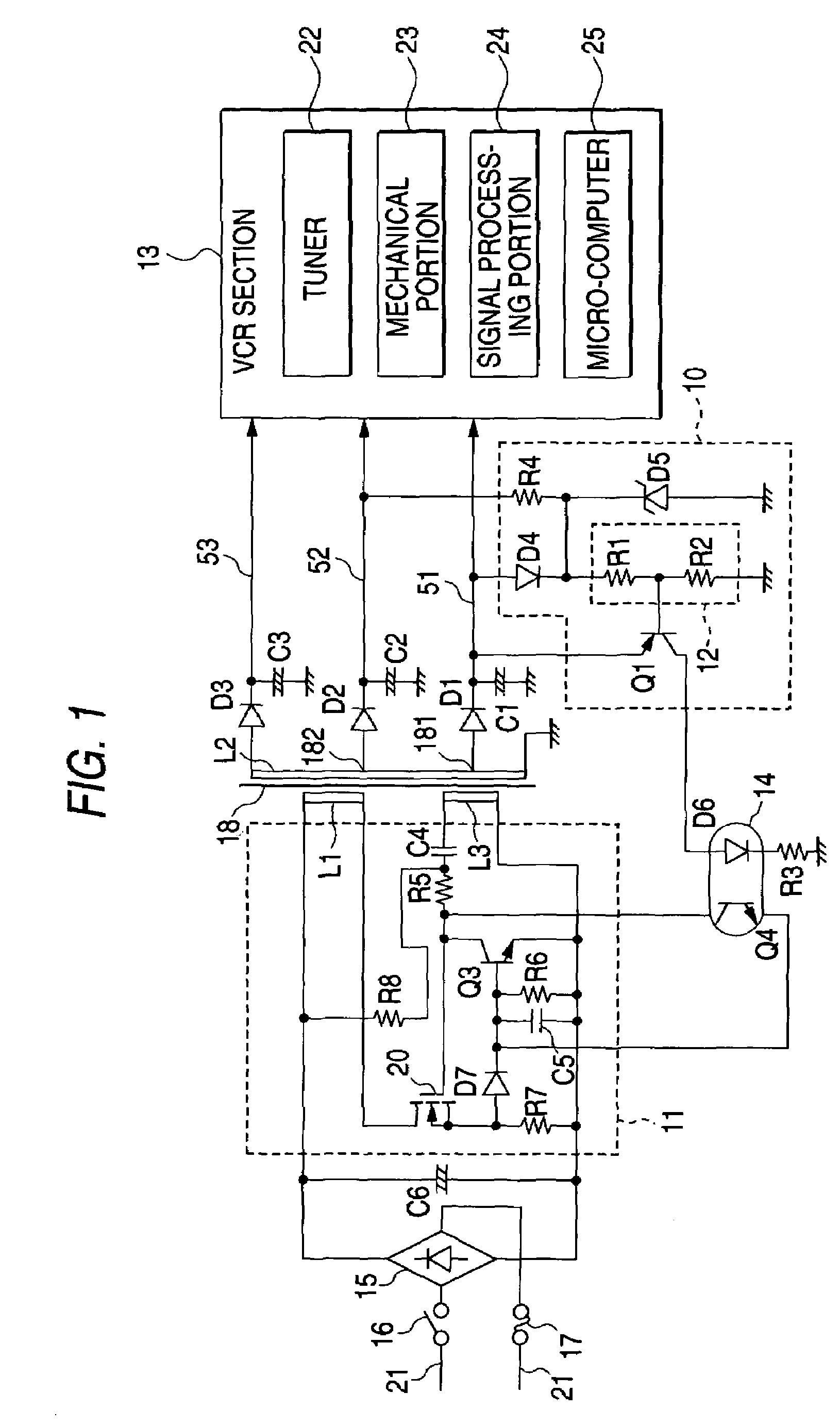
[0018]FIG. 1 is a circuit diagram showing electrical connection in an RCC type switching power supply according to an embodiment of the device in the case where the RCC (Ringing Choke Converter) type switching power supply is applied to a video cassette recorder.

[0019]In FIG. 1, a commercial power source 21 is rectified and smoothed by a diode bridge 15 and a capacitor C6 to thereby generate a primary side DC source. A plus level of the primary side DC source is connected to one terminal of a primary coil L1 wound on a transformer 18. A drain of an FET 20 which is a switching element is connected to the other terminal of the primary coil L1. One terminal of a drive coil L3 wound on the transformer 18 is connected to a gate of the FET 20 through a capacitor C4 and a resistor R5 for coupling. A source of the FET 20 is connected to a minus level (hereinafte...


PUM


Abstract

An error detection circuit includes: a Zener diode having a cathode connected through a resistor to a second DC output with a higher voltage than that of a first DC output; a voltage divider circuit; and a PNP transistor having an emitter connected to the first DC output, and a base supplied with an output voltage of the voltage divider circuit. A Zener voltage of the Zener diode and a voltage dividing ratio of the voltage divider circuit are set so that the output voltage of the voltage divider circuit is equal to a value obtained by subtracting the base-emitter voltage of the PNP transistor Q1 from the voltage of the first DC output, and that temperature characteristic of the output voltage of the voltage divider circuit is set at a value canceling temperature characteristic of the PNP transistor.

Description

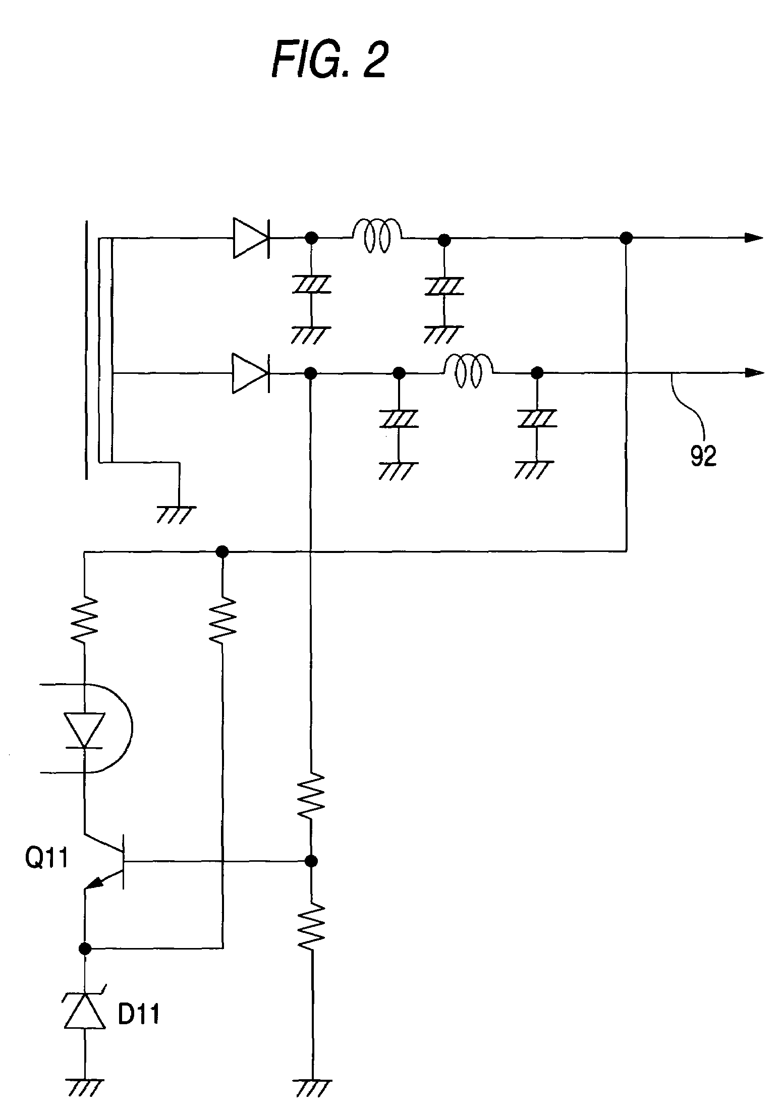
BACKGROUND OF THE INVENTION[0001]1. Field of the Invention[0002]The present invention relates to an RCC (Ringing Choke Converter) type switching power supply in which a voltage error of a DC output is detected on the basis of a reference voltage generated by a Zener diode, and a video cassette recorder equipped with the RCC type switching power supply.[0003]2. Description of the Related Art[0004]A configuration in which a reference voltage stabilized by a Zener diode D11 is led to an emitter of a transistor Q11 as shown in FIG. 2 is used for detecting a voltage error of a DC output in a switching power supply or the like. In this case, the voltage range of a DC output 92 allowed to be subjected to error detection is limited to a voltage range higher than the sum of the Zener voltage and the base-emitter voltage of the transistor Q11 for detecting an error. On the other hand, good temperature characteristic can be obtained when temperature characteristic of the base-emitter voltage o...

Claims


Application Information

Patent Timeline
IPC IPC(8): H02H7/122G11B15/00H04N5/76H04N5/781
CPCG11B15/00H02M3/338H02M2001/009H02M1/009
Inventor OGAWA, TAKAHIRO
Owner FUNAI ELECTRIC CO LTD
Learn More