
Structural environmentally-protective coating

Inactive Publication Date: 2007-04-24
GENERAL ELECTRIC CO
View PDF7 Cites 5 Cited by
  • Summary
  • Abstract
  • Description
  • Claims
  • Application Information

AI Technical Summary

Benefits of technology

[0008]The present invention generally provides a coating suitable for use as an environmentally-protective coating on surfaces of components used in hostile thermal environments, including the turbine, combustor and augmentor sections of a gas turbine engine. Such coatings include environmental coatings that form the outmost surface of a component, and bond coats that adhere a TBC to the component. The invention is particularly directed to coatings with sufficient strength, as measured in terms of tensile or rupture strength, to enable the coating to contribute to the strength of the component on which the coating is deposited.
[0010]The coating of this invention has desirable environmental and mechanical properties that render it useful as an environmental coating and as a bond coat for a TBC. In particular, as a result of being predominantly platinum, rhodium, palladium, and / or iridium, the coating exhibits greater oxidation resistance than the superalloy substrate it protects. In contrast to conventional environmental coatings and bond coats, the coating also exhibits sufficient strength so that, for example, the combination of the superalloy substrate and coating may exhibit a combined strength of at least 90% of the strength that would exist if the combined thickness of the coating and substrate were formed entirely by the superalloy of the substrate. The strength of the coating can be further promoted with additions of one or more transition elements (particularly zirconium, hafnium, titanium, tantalum, niobium, chromium, tungsten, molybdenum, rhenium, and / or ruthenium). In addition, the environmental resistance and thermal (diffusional) stability of the coating can be promoted with additions of aluminum, chromium, and / or nickel.

Problems solved by technology

However, a thermal expansion mismatch exists between metallic bond coats, their alumina scale and the overlying ceramic TBC, and peeling stresses generated by this mismatch gradually increase over time to the point where TBC spallation can occur as a result of cracks that form at the interface between the bond coat and alumina scale or the interface between the alumina scale and TBC.
Though having the above-noted benefits, there are drawbacks to the use of environmental coatings and bond coats.
For example, the maximum design temperature of a coated component is typically limited by the maximum allowable temperature of its environmental coating or bond coat (in the event of TBC spallation).
A low melting point zone also tends to form between such coatings and their underlying superalloy substrate, further limiting the high temperature capability of the component.
Another drawback is that the materials used to form environmental coatings and bond coats are relatively weak compared to the nickel and cobalt-base superalloys that form the components they protect.
As a result, these coatings are considered dead weight that must be supported by the superalloy substrate, which is particularly detrimental to rotating airfoil applications such as turbine blades where the effect is greatly multiplied by the high G-field under which such components operate.
As a result, airfoil components must be designed to be sufficiently strong to carry the weight of the coatings, often incurring yet additional weight penalty.

Method used


Image

  • Structural environmentally-protective coating
  • Structural environmentally-protective coating

Examples


Embodiment Construction

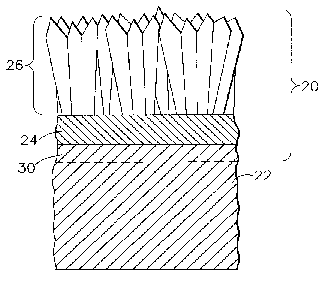
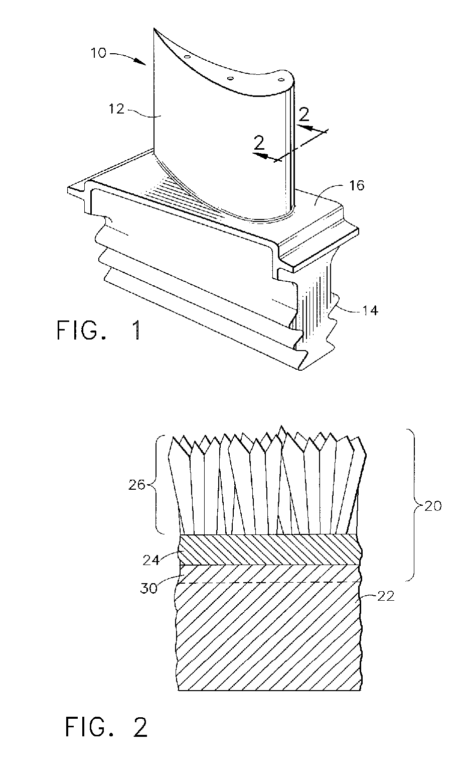
[0014]The present invention is generally applicable to components that operate within environments characterized by relatively high temperatures, and are therefore subjected to severe thermal stresses and thermal cycling. Notable examples of such components include the high and low pressure turbine nozzles and blades, shrouds, combustor liners and augmentor hardware of gas turbine engines. Of particular interest are components that must withstand high g-forces, such as rotating airfoil components of gas turbine engines. One such example is a high pressure turbine blade 10 shown in FIG. 1. The blade 10 includes an airfoil 12 against which hot combustion gases are directed during operation of the gas turbine engine. The airfoil 12 is hollow to permit the flow of cooling air through passages within the blade 10, with the result that the exterior of the airfoil 12 is generally defined by walls whose outer surfaces are subjected to severe attack by oxidation, corrosion, and erosion and w...


PUM

PropertyMeasurementUnit
Temperatureaaaaaaaaaa

Abstract

A coating suitable for use as an environmentally-protective coating on surfaces of components used in hostile thermal environments, including the turbine, combustor and augmentor sections of a gas turbine engine. The coating is used in a coating system deposited on a substrate formed of a superalloy material. The coating contacts a surface of the superalloy substrate and is formed of a coating material having a tensile strength of more than 50% of the superalloy material. The coating material is predominantly at least one metal chosen from the group consisting of platinum, rhodium, palladium, and iridium, and has sufficient strength to significantly contribute to the strength of the component on which the coating is deposited.

Description

BACKGROUND OF THE INVENTION[0001]This invention relates to coatings of the type used to protect components exposed to high temperature environments, such as the hostile thermal environment of a gas turbine engine. More particularly, this invention is directed to protective coatings that are capable of significantly contributing to the structural properties of the components they protect.[0002]Certain components of the turbine, combustor and augmentor sections susceptible to damage by oxidation and hot corrosion attack are typically protected by an environmental coating and optionally a thermal barrier coating (TBC), in which case the environmental coating is termed a bond coat that in combination with the TBC forms what may be termed a TBC system. Environmental coatings and TBC bond coats are often formed of an oxidation-resistant aluminum-containing alloy or intermetallic whose aluminum content provides for the slow growth of a strong adherent continuous aluminum oxide layer (alumi...

Claims


Application Information

Patent Timeline
IPC IPC(8): B32B15/01B32B15/04B32B15/18
CPCC23C4/06C23C28/00C23C30/00C23C28/321C23C28/3215C23C28/3455C23C28/325Y10T428/264Y10T428/12944Y10T428/12875Y10T428/12951Y10T428/26
Inventor GORMAN, MARK DANIELDAROLIA, RAMGOPAL
Owner GENERAL ELECTRIC CO
Learn More