Mass spectrometer
a mass spectrometer and mass range technology, applied in the field of mass spectrometers, can solve the problems of significantly increasing the cost, unable to obtain a duty cycle of 40% or less, and the mass range which can obtain a high duty cycle is extremely limited, so as to achieve high mass accuracy and high sensitivity
- Summary
- Abstract
- Description
- Claims
- Application Information
AI Technical Summary
Benefits of technology
Problems solved by technology
Method used
Image
Examples
embodiment 1
(Embodiment 1)
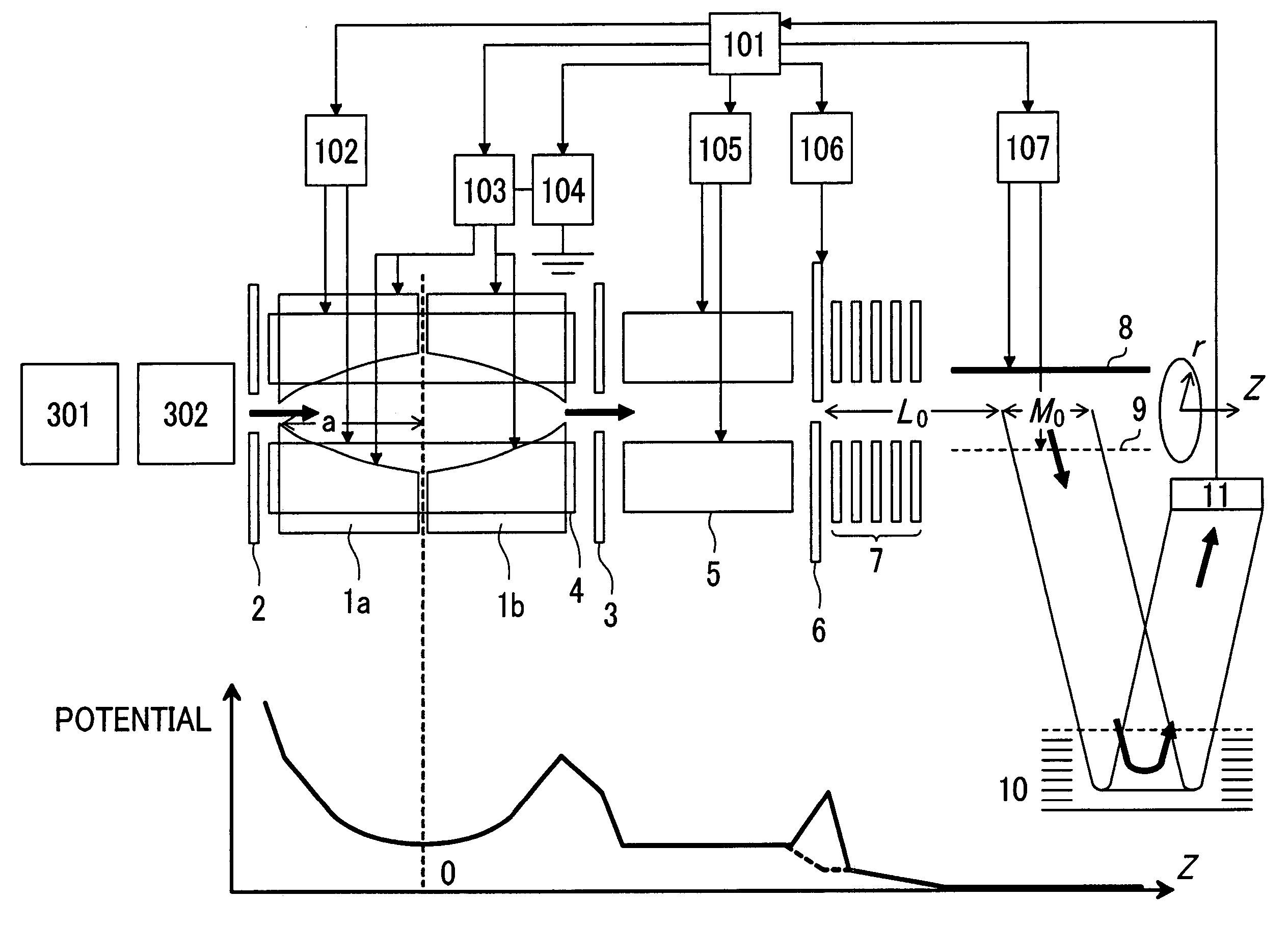
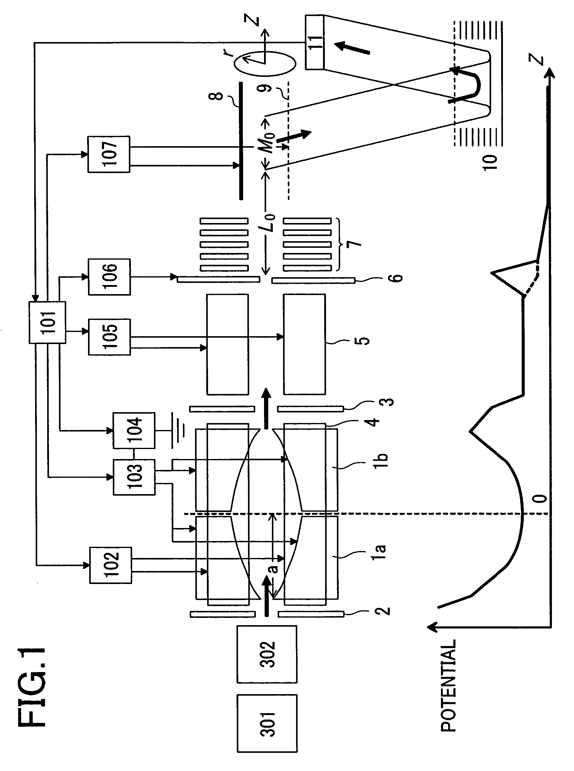
[0043]FIG. 1 shows a block diagram of a time-of-flight mass spectrometer according to a first embodiment of the present invention. The pumping device such as a pump and the buffer gas introducing mechanism are omitted for simplification.
[0044]Ions generated by an ionization source 301 such as an electrospray ionization source, a matrix assisted laser desorption ionization source, an atmospheric pressure chemical ionization source, an atmospheric pressure photoionization source, or an atmospheric pressure matrix assisted laser desorption ionization source are introduced via an ion transfer optics 302 having an octapole, a quadrupole mass filter, or a quadrupole ion trap or a multipole linear trap permitting accumulation, isolation, and dissociation and an inlet electrode 2 into a first linear trap. The detail of the first linear trap is described in the previously described Conventional Method (Patent Document 3).
[0045]The first linear trap has an inlet electrode 2, an ...
embodiment 2
(Embodiment 2)
[0070]The ion quantity which can be accumulated in the first linear trap is limited. In order not to be affected by space charge, faster measurement is desired.
[0071]A second embodiment of the present invention making measurement faster will be described. The construction of the apparatus is almost the same as the first embodiment (FIG. 1). A supplemental AC power supply 103 can generate the superimposed waveform of a plurality of RF voltages.
[0072]FIG. 9 shows its measurement sequence. The later-described supplemental AC voltage is applied between vane electrodes 1a and 1b during T0. Only ions in the specific mass range are transferred from the first linear trap to the second linear trap. T1 and T2 are fixed during certain fixed time T3 (about 10 ms) from the start of measurement for detection. Time T3 setting the fixed T1 and T2 is defined as one scan for performing plural scans.
[0073]FIG. 10 shows target maximum mass and target minimum mass in each scan for measurin...
embodiment 3
(Embodiment 3)
[0076]Embodiment 3 of the present invention will be described using FIG. 13. In this embodiment, a first linear trap 16 and a second linear trap 17 use the same multipole rods 12 to make the apparatus simplifier and the cost lower. In FIG. 13, the pumping device such as a pump and the buffer gas introduction mechanism are omitted for simplification.
[0077]Ions generated by an ionization source 301 such as an electrospray ionization source, an atmospheric pressure chemical ionization source, an atmospheric pressure photoionization source, or an atmospheric pressure matrix assisted laser desorption ionization source are introduced via an ion transfer optics 302 having an octapole, a quadrupole mass filter, or a multipole linear trap and an inlet electrode 2 into a first linear trap 16. The first linear trap 16 has the inlet electrode 2, four, six or eight multipole rods 12 (in this example, quadrupole rods are shown), and part of the region surrounded by vane electrodes 1...
PUM
 Abstract
Description
Claims
Application Information
 - R&D
- Intellectual Property
- Life Sciences
- Materials
- Tech Scout
- Unparalleled Data Quality
- Higher Quality Content
- 60% Fewer Hallucinations
Browse by: Latest US Patents, China's latest patents, Technical Efficacy Thesaurus, Application Domain, Technology Topic, Popular Technical Reports.
© 2025 PatSnap. All rights reserved.Legal|Privacy policy|Modern Slavery Act Transparency Statement|Sitemap|About US| Contact US: help@patsnap.com


