Alkali ion conductive glass-ceramics and electric cells and gas sensors using the same

a technology electric cells, applied in the field of alkali ion conductive glassceramics and electric cells and gas sensors using the same, can solve problems such as conductivity drop, and achieve the effect of high performan

Inactive Publication Date: 2007-05-01
OHARA
View PDF9 Cites 90 Cited by
  • Summary
  • Abstract
  • Description
  • Claims
  • Application Information

AI Technical Summary

Benefits of technology

[0015]It is another object of the invention to provide an alkali cell and a gas sensor of a high performance by utilizing such glass-ceramics.

Problems solved by technology

These ceramics, however, have pores and a large grain boundary which can not be eliminated completely and existence of these pores and grain boundary results in a decrease in conductivity.

Method used


Image

  • Alkali ion conductive glass-ceramics and electric cells and gas sensors using the same
  • Alkali ion conductive glass-ceramics and electric cells and gas sensors using the same
  • Alkali ion conductive glass-ceramics and electric cells and gas sensors using the same

Examples


example 1

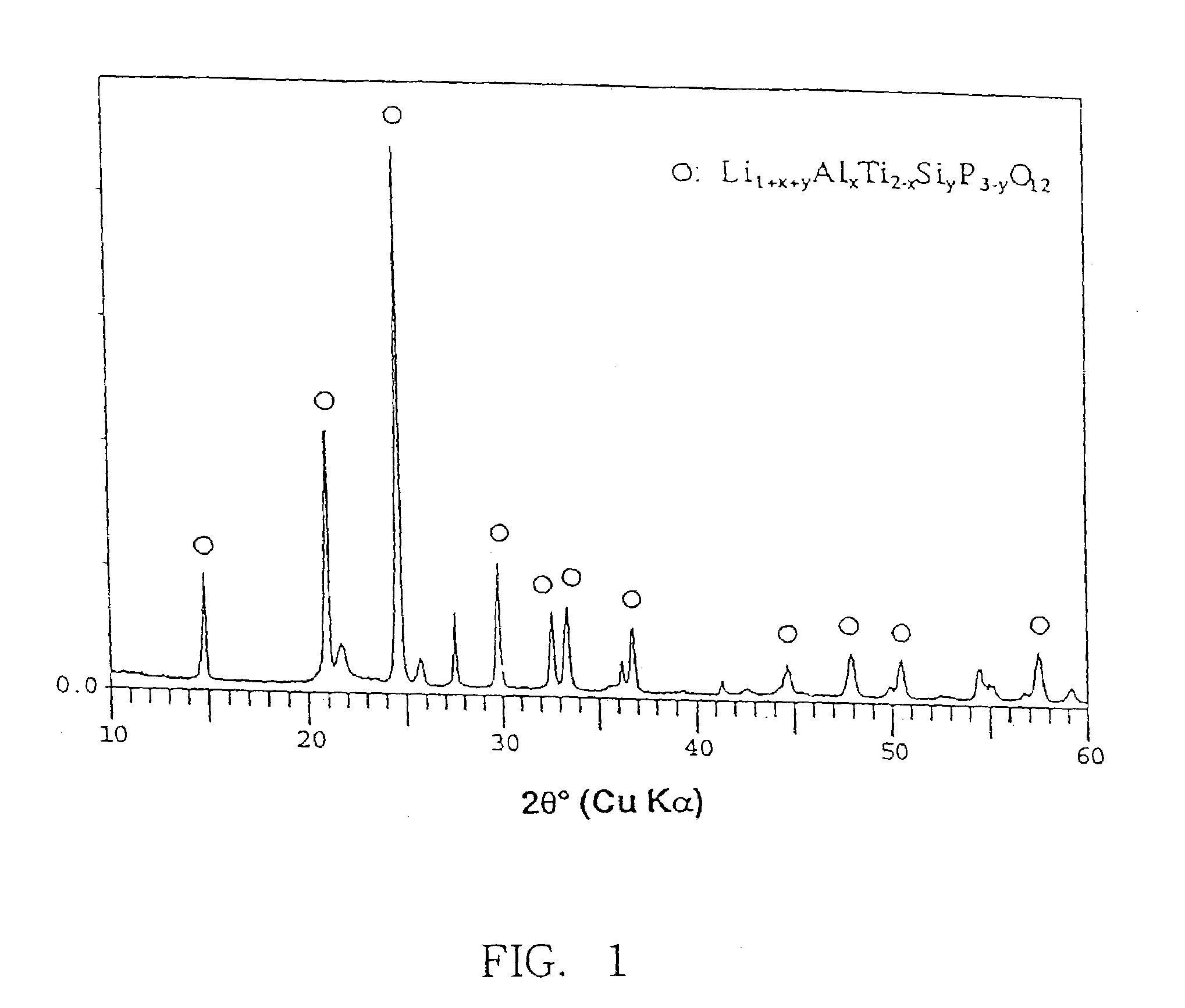
[0072]As starting materials, NH4H2PO4, TiO2, Al(OH)3 and Li2CO3 were used. These starting materials were weighed to constitute a composition of 39P2O5-8.5Al2O3-39TiO2-13.5Li2O in mol %. The materials were mixed uniformly and then put in a platinum crucible and heated and melted in an electric furnace. First, CO2, NH3 and H2O coming from the raw materials were evaporated at 700° C. Then the temperature was raised to 1450° C. and the materials were melted by heating them at this temperature for 1.5 hour. Thereafter, the melt was cast onto a stainless steel plate to form a uniform sheet glass. The glass was annealed at 550° C. for two hours for removing thermal stress of the glass.

[0073]The glass thus produced was cut into specimens each having the size of 20×20 mm. The specimens of glass were polished on both surfaces and subjected to heat treatment under various heat conditions. The crystal phase which precipitated in the specimens was determined by the powder X-ray diffraction metho...

example 2

[0074]As the starting materials, NH4H2PO4, TiO2, Al(OH)3, Ga2O3 and Li2CO3 were used to produce a glass-ceramic by employing the same manner as in Example 1. The crystal phase which grew in specimens of this glass-ceramic was determined to be Li1+X(Al, Ga)XTi2−X(PO4)3. The specimen which was heat treated at 950° C. for 12 hours exhibited the highest conductivity of 1.0×10⁻³S / cm (Table 1, Example No.2).

[0075]

TABLE 1(composition in mol %)ExamplesNo.12P2O53939TiO23938Al2O38.56.5Ga2O32.5Li2O13.514coductivity at room1.3 ×1.0 ×temperature (S / cm)10−310−3temperature of1000950heat treatment (° C.)time of1212heat treatment (Hr)

example 3

[0076]As starting materials, NH4H2PO4, SiO2, TiO2, Al(OH)3 and Li2CO3 were used. These starting materials were weighed to constitute a composition of 32P2O5-8SiO2-41TiO2-5Al2O3-14Li2O in mol %. The materials were mixed uniformly and then put in a platinum crucible and heated and melted in an electrical furnace. First, CO2, NH3 and H2O coming from the raw materials were evaporated at 700° C. Then the temperature was raised to 1450° C. and the materials were melted by heating them at this temperature for 1.5 hour. Thereafter, the melt was cast onto a stainless steel plate to form a uniform sheet glass. The glass was annealed at 550° C. for two hours for removing thermal stress of the glass.

[0077]The glass thus produced was cut into specimens each having the size of 20×20 mm. The specimens of glass were polished on both surfaces and subjected to heat treatment at a temperature of 800° C. for 12 hours and then at 1000° C. for 24 hours to produce a dense glass-ceramic. The crystal phase ...


PUM

PropertyMeasurementUnit
conductivityaaaaaaaaaa
decomposition voltageaaaaaaaaaa
conductivityaaaaaaaaaa

Abstract

There are provided glass-ceramics having a high lithium ion conductivity which include in mol %:

P2O5
38–40%
TiO2
25–45%
M2O3 (where M is Al or Ga)
 5–15%
Li2O
10–20%
and contain Li1+X(Al, Ga)XTi2−X(PO4)3 (where 0<X<0.8) as a main crystal phases. There are also provided glass-ceramics having a high lithium ion conductivity which include in mol %:

P2O5
 26–40%
SiO2
0.5–12%
TiO2
 30–45%
M2O3 (where M is Al or Ga)
  5–10%
Li2O
 10–18%
and contain Li1+X+YMXTi2−XSiYP3−YO12 (where 0<X≦0.4 and 0<Y≦0.6) as a main crystal phase. There are also provided solid electrolytes for an electric cell and a gas sensor using alkali ion conductive glass-ceramics, and a solid electric cell and a gas sensor using alkali ion conductive glass-ceramics as a solid electrolyte.

Description

[0001]This application is a continuation of Ser. No. 09 / 614,948, filed Jul. 12, 2000, now abandoned, which is a continuation of Ser. No. 08 / 923,233, filed Sep. 4, 1997, abandoned, which is a continuation in part of Ser. No. 08 / 741,704, filed Oct. 31, 1996, now U.S. Pat. No. 5,702,995, which claims priority under 35 U.S.C. § 119 to Japanese Application Nos. 320971 / 1995, filed Nov. 15, 1995; 115694, filed Apr. 12, 1996; and 38303 filed Feb. 6, 1997.BACKGROUND OF THE INVENTION[0002]This invention relates to an alkali ion conductive glass-ceramics and, more particularly, to a lithium ion conductive glass-ceramics suitable for use as wholly solid electric cells, gas sensors and electrochemical devices of various types, and electric cells and gas sensors using such glass-ceramics.[0003]Recent development in electronics has brought about high-performance electronic devices of a compact and light-weight design and, as a power source of such electronic devices, development of an electric cel...

Claims


Application Information

Patent Timeline
Patent Type & Authority Patents(United States)
IPC IPC(8): C03C10/02C03C4/14C03C4/18C03C10/00G01N27/407H01M10/36
CPCC03C4/18C03C10/00C03C10/0009C03C10/0027G01N27/4074H01M10/0525H01M10/0562Y02E60/122Y02E60/10
Inventor FU, JIE
Owner OHARA
Why Eureka
Try Eureka