Rankine-microturbine for generating electricity

a micro-turbine and power generation technology, applied in the direction of electric generator control, machines/engines, mechanical equipment, etc., can solve the problems of high maintenance cost of power plants, too complex and expensive for smaller power plants, and low electrical output power efficiency for opportunities in main power applications, etc., to achieve high electrical output power efficiency, reduce installation cost, and reduce emissions. the effect of co2 emission

Inactive Publication Date: 2007-05-01
T M A POWER
View PDF8 Cites 32 Cited by
  • Summary
  • Abstract
  • Description
  • Claims
  • Application Information

AI Technical Summary

Benefits of technology

[0008]In view of the foregoing disadvantages inherent in the known type of microturbines now present in the prior art, the present invention provides a new combined cycle system, the Rankine-Microturbine incorporating a microturbine wherein the same can be utilized for providing a combined cycle turbine system having a common shaft between the steam turbine and the gas turbine integral alternator rotor, a one spool rotor system, to yield high electrical output power efficiency, simplicity, reduced installation cost and reduced emissions specie CO2 thru reduced fuel usage.
[0013]A primary object of the present invention is to provide a rankine-microturbine combined cycle system that will overcome the shortcomings of the prior art devices. An object of the present invention is to provide a rankine-microturbine combined cycle system with a common shaft between the steam turbine and the gas turbine integral alternator rotor as a one spool rotor system to yield high cycle efficiency and simplicity with reduced installation cost.
[0014]Another object is to provide a rankine-microturbine that yields a high electrical power cycle efficiency in a combined cycle turbine electrical power generator in the microturbine class having one common generator / alternator driven by the gas turbine and stream turbine.
[0015]Another object is to provide a ranking-microturbine that offers more durability, less maintenance, less operating cost and greater cycle efficiency than any piston type internal combustion engine electrical power generator.
[0016]Another object is to provide a rankine-microturbine that offers on site stand alone low cost electric power for home owners, industry and business as main power, emergency or standby applications.

Problems solved by technology

Microturbines (non synchronous generators), typically less than 500 Kw offer some advantages either in line tie or island system especially in a CHP cycle but still lack high electrical output power efficiencies for opportunities in main power applications.
Combined cycle electrical power systems have synchronous power generators and are large power-plants and have either separate generators for the steam and gas turbines or more recently use a clutch coupled steam turbine and gas turbine to drive a common generator yielding >60% electrical output power efficiency; but are too complex and expensive for smaller power-plant applications.
Complexity will lend to higher power plant maintenance cost even thou the fuel cost is the biggest factor in the $ / Kw-hr billing.
Another issue with conventional microturbines is the use of heat exchanger to attain ˜30 efficiency is still too low for distributed continuous main power applications and with the heat exchanger there are limitations on start-up and shut-down cycles concerning turbine exhaust gas temperature as high as 1300F and material costs life cycle considerations.
A hybridmicroturbine with its staged higher compressor ratio (˜23% at maximum power) has higher efficiency at off design than that of the microturbine with heat exchanger and does not have start up or shut down limitation like this microturbine; but due to the lower efficiency, has limited main grid power uses.
While these devices may be suitable for the particular purpose to which they address, they are not as suitable for providing a combined cycle turbine system with a common shaft between the steam turbine and the gas turbine integral alternator rotor as a one spool rotor system to yield high electrical power cycle efficiency, simplicity, reduced installation cost and maintenance.

Method used


Image

  • Rankine-microturbine for generating electricity
  • Rankine-microturbine for generating electricity
  • Rankine-microturbine for generating electricity

Examples


Embodiment Construction

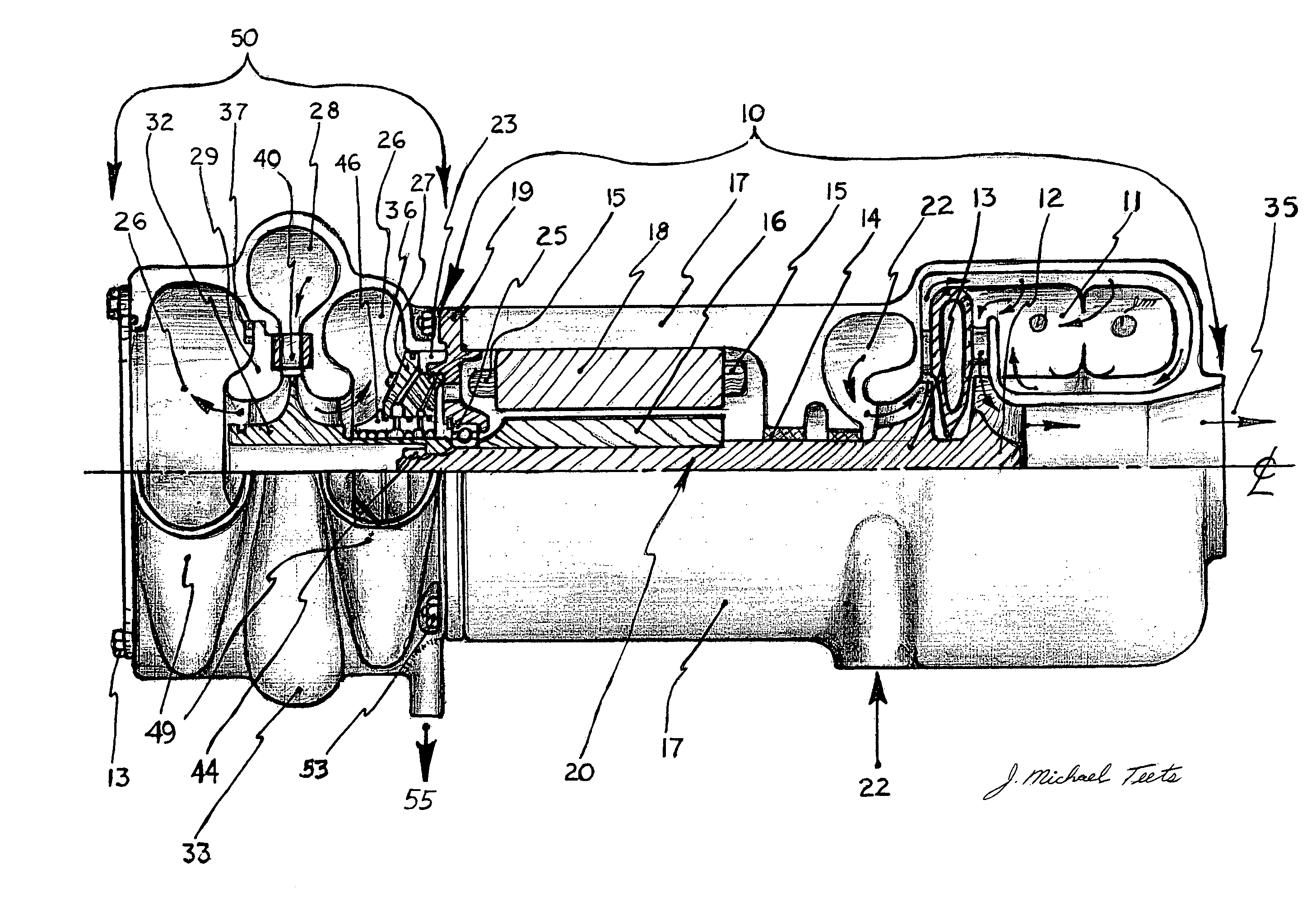
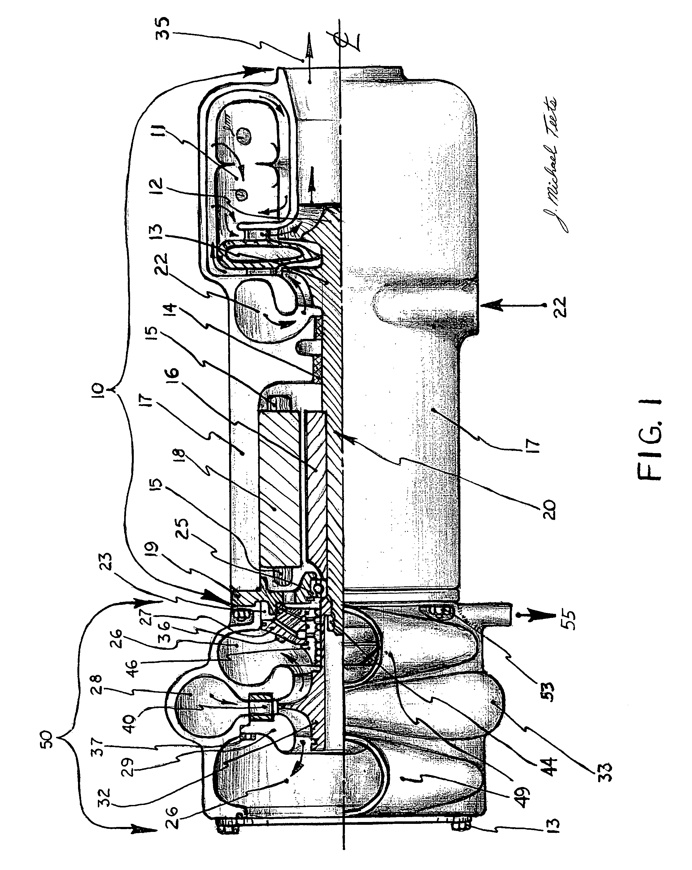
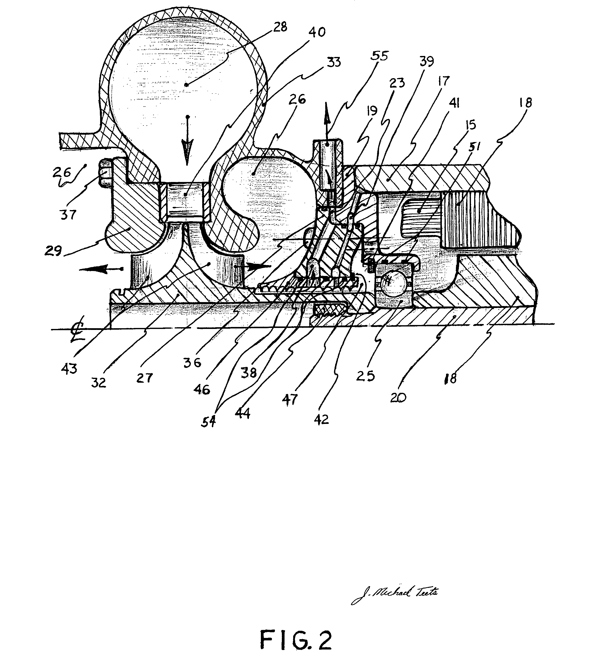
[0024]Turning now descriptively to the drawings, in which similar reference characters denote similar elements throughout the several views, the attached figures illustrate a Rankine-Microturbine system, which comprises a Microturbine or Hybrid-Microturbine, a Steam Turbine Seal, a Steam Turbine Seal Support, a Steam Turbine Housing, a Steam Turbine Nozzle, a Steam Turbine Rotor, a Steam Turbine Shroud, and Steam Housing Cap. The Microturbine has one gas turbine rotor—compressor rotor—alternator rotor assembly spool with retained rotor magnet that are positioned coaxially within an electrical stator for electric power. A Hybrid-Microturbine is a microturbine without a turbine exhaust heat exchanger and incorporates a turbocharger to extract energy from the microturbine exhaust for a multistage high pressure engine compressor. The Steam Turbine Seal is a static device that prevents exhaust steam from entering the rotor spool bearing cavity and minimizes the steam leakage past the ste...


PUM


Abstract

An electrical output power generation system is provided. A gas turbine engine rotor spool with at least one alternator rotor and steam turbine rotor are integrated and within a engine body having a combustor or external heat source having fluid communication with the bladed compressor rotor and a gas turbine bladed rotor of the said rotor spool. The alternator rotor has permanent magnets retained and positioned in close proximity and co-axial to the electrical stator having iron laminat and electrical wires. Relative rotational motion between the electrical stator and alternator rotor cause magnetic flux and subsequent electricity to be generated. The steam energy to drive the said rotor spool integrated steam turbine rotor can be from the gas turbine engine exhaust waste heat and or thru external heat energy sources.

Description

[0001]This application claims benefit of the provisional application Ser. No. 60 / 668,127 filed Apr. 4, 2005.BACKGROUND OF THE INVENTION[0002]1. Field of the Invention[0003]This invention relates generally to gas turbine electrical power generation and more specifically to a rankine-microturbine as a combined cycle turbine system having a common rotor shaft, incorporating a steam turbine with a gas turbine rotor spool with an integral alternator rotor in close proximity and co-axially within a laminated iron stator with wires to generate electricity.[0004]2. Description of Prior Art[0005]It can be appreciated that microturbines, a non-synchronous electrical power generator, have been in use for years. Typically, microturbines are comprised of gas turbines such as in U.S. Pat. Nos. 6,314,717, 6,605,928, 5,497,615 and Japanese patent 061737714 and currently demonstrate <30% cycle efficiency incorporating heat exchangers, <15% cycle efficiency without heat exchangers and the hybri...

Claims


Application Information

Patent Timeline
Patent Type & Authority Patents(United States)
IPC IPC(8): F01D15/10
CPCF01D15/10F02C6/18F05D2250/82Y02E20/14F05D2260/85F05D2220/76F05D2220/72
Inventor TEETS, JOSEPH MICHAELTEETS, JON WILLIAM
Owner T M A POWER
Why Eureka
Try Eureka