
Method and device for pyrolyzing and gasifying organic substances or substance mixtures

Inactive Publication Date: 2007-05-08
HERHOF UMWELTTECHN
View PDF6 Cites 65 Cited by
  • Summary
  • Abstract
  • Description
  • Claims
  • Application Information

AI Technical Summary

Benefits of technology

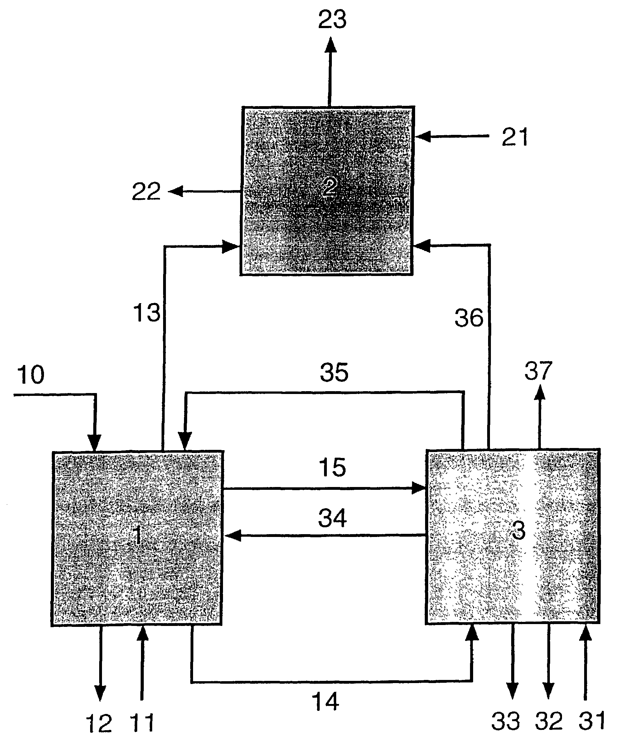
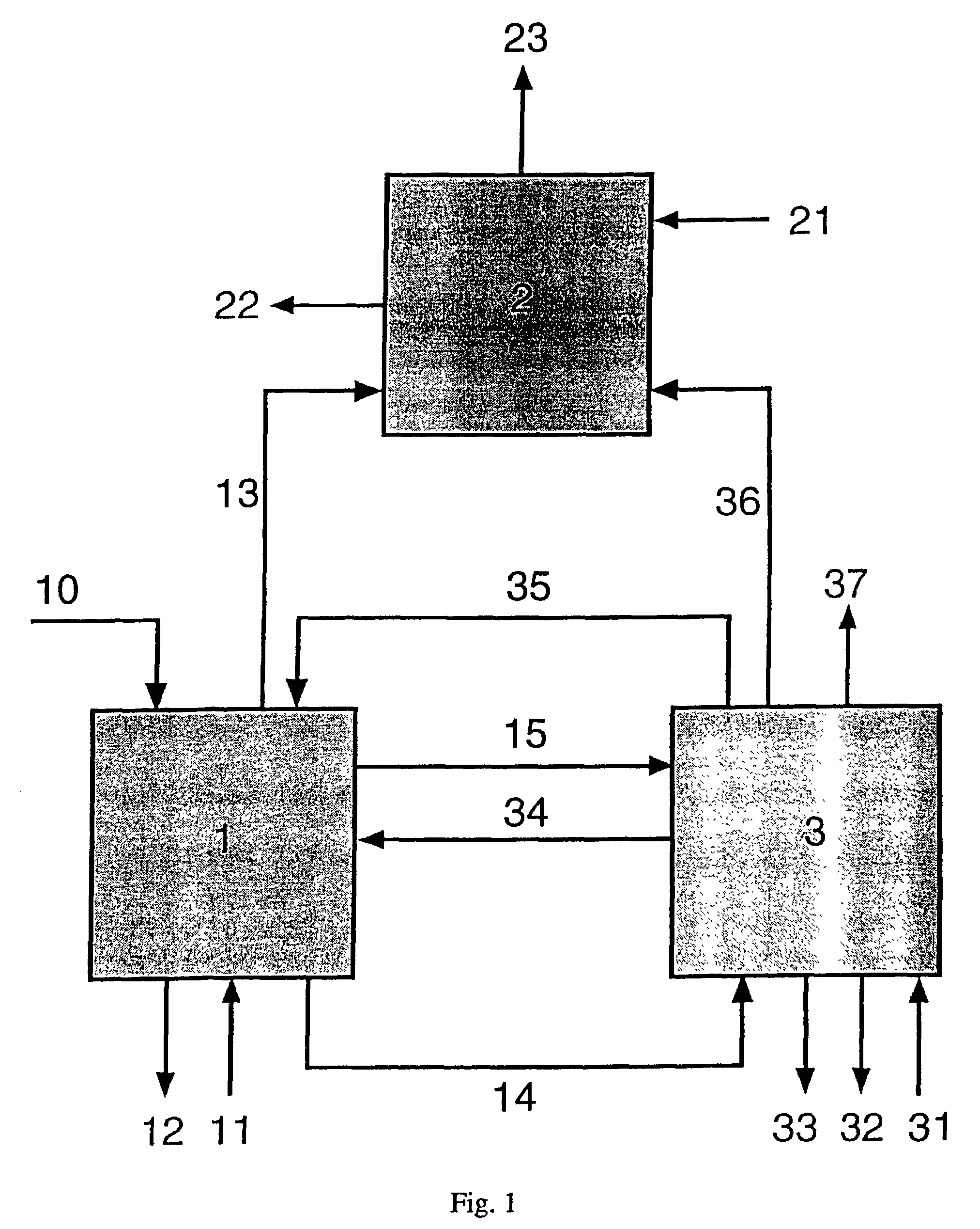
[0012]Due to the fact that the pyrolysis is preferably carried out in a shaft oven, the supply of a fluidizing medium required for a pyrolysis fluidized-bed can be omitted. In this way, the possibility exists to carry out the pyrolysis completely without supplying gas or, unlike a pyrolysis fluidized-bed to which a minimum amount of gas must be supplied for fluidizing, to add any desired low amounts, for example of the product gas or of a gasification agent such as steam, oxygen or air. In this way, the possibility exists to add gas or a gasification agent to the pyrolysis reactor as a technical method adaptation to the respective application material. In the method of the invention, the pyrolysis is preferably carried out in the pyrolysis reactor in the absence of air and of gas. Another advantage of the carrying out of the pyrolysis in a separate process stage consists of the crushing effect which occurs during pyrolysis, allowing the use of coarser fragmentary material than normally used in fluidized-bed reactors due to the smouldering and degassing. Alternatively, the possibility exists of interposing a crushing apparatus such as a roller crusher before the carrying-in apparatus for the solid carbonaceous pyrolysis residue and the fluidized-bed material into the combustion fluidized-bed, whereby the demands on the application material particle sizes can be further reduced. The energy to be used for the crushing of pyrolysis coke is here substantially lower than that for the crushing of, for example, biomass such as wood.
[0013]The carbonaceous solid pyrolysis residue is incinerated with air in the fluidised bed, itself thereby becomes fluidised-bed material as ash and, due to the energy release, further heats up or again heats up fluidised-bed material already present. The combustion fluidised bed can be designed and operated according to the level of knowledge of fluidised bed technology. A stepped addition of air can be advantageous with respect to the emissions of the combustion fluidised bed. The combustion reactor is designed as a stationary fluidised bed, that is the gas amount of the fluidised medium must be sufficient, on the one hand, to exceed the minimum fluidisation rate of the solid and must not, on the other hand, exceed the speed for the yield. From a fluidised bed height of approximately 2.5 m to 3 m, fixed equipment is required to prevent the formation of a pulsing fluidised bed and the accompanying pressure pulsations. The fluidised-bed material heated up by the combustion procedure is finally again supplied to the pyrolysis reactor. The fluidised-bed material consists of the ash which remains from the incineration of the solid carbonaceous residue. If an incomplete combustion of the pyrolysis coke within the combustion fluidised bed takes place, the fluidised-bed material which is guided in the circuit as the heat transfer medium consists of the ash of the application material and of unburned carbonaceous pyrolysis residue. As the solid carbonaceous residues of the organic substances and mixtures of organic substances as a rule transform rapidly in the combustion fluidised bed and in part can only have low portions of material which cannot be gasified or incinerated, it is optionally necessary to add additional material in order to form a fluidised bed. Additional material does not need to be added if the application materials have large amounts of material which cannot be gasified or incinerated, which are suitable to build up a fluidised bed. All refractory materials such as sand with a grain diameter of less than 1.5 mm are suitable as the material to be added which serves to form a fluidised bed. The removal of the hot fluidised-bed material and the transport into the pyrolysis reactor is preferably effected by means of one or more overflows which are provided at the reactor wall or project through the reactor wall into the fluidised bed. The method has the advantage that, in addition to the transfer of the hot fluidised-bed material into the pyrolysis reactor, the fluidised bed height of the combustion fluidised bed can be set in a simple manner. The removal of the fluidised-bed material can also be carried out by means of other known conveyors such as a screw conveyor; however in this case the technical method effort is higher.

Problems solved by technology

The majority of known gasification methods is not suitable for smaller, decentralised systems due to the high apparatus effort.
Extremely higher demands on the preparation of the fuel result in the case of entrained-bed gasification which only allows the use of pulverised fuel particles.
Further substantial disadvantages of the known gasification methods are that the proceeding process stages of drying, degassing, gasification and incineration of the application material proceed in zones which are directly next to one another and which merge into one another.
As a result, the individual zones within a reactor are undefined and the degassing, gasification and incineration can proceed incompletely at points.
When fuels with a high content of volatile components and a low pyrolysis coke yield are used, there is a risk of an insufficient formation of the glow bed of the gasification reactor consisting of pyrolysis coke, whereby the oxidation of the carbon to CO with a simultaneous reduction of waste gas and steam to a combustible lean gas proceeds insufficiently at the cost of the product gas calorific value.
The operation of the fluidised beds requires a high effort and a control of the reactions of the pyrolysis gases in the reaction zone is hardly possible.

Method used


Image

  • Method and device for pyrolyzing and gasifying organic substances or substance mixtures
  • Method and device for pyrolyzing and gasifying organic substances or substance mixtures
  • Method and device for pyrolyzing and gasifying organic substances or substance mixtures

Examples


embodiment

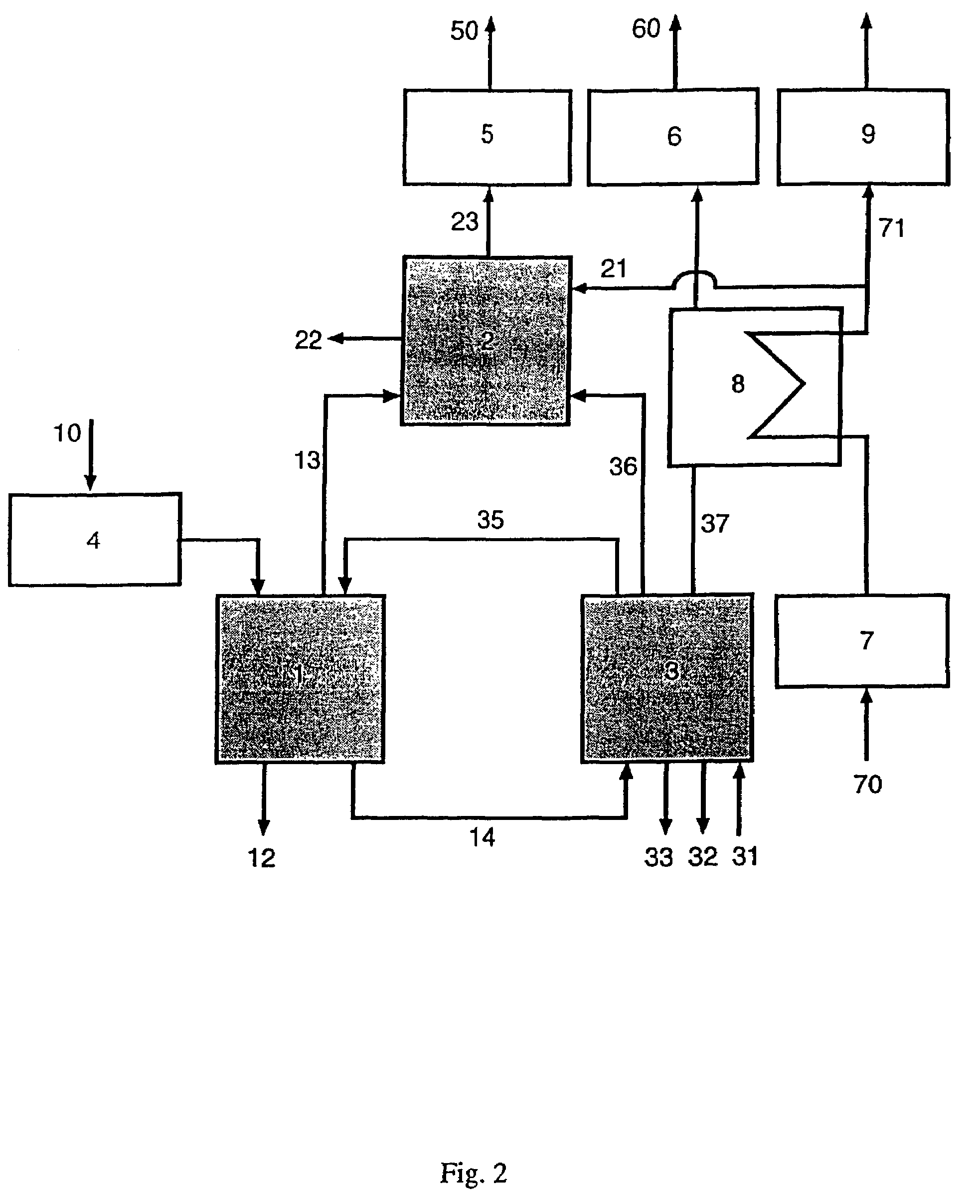
[0022]In the following example, the preferred design of the method of the invention and of the apparatus of the invention is described. The preferred method in accordance with FIG. 2 and the preferred apparatus in accordance with FIG. 3 serves for the pyrolysis and gasification of 900 kg of wood per hour. The wood used as an example substantially consists of 52.3 percent by weight of carbon, 5.9 percent by weight of hydrogen and 41.8 percent by weight of oxygen, in each case with respect to the fuel substance free of water and ash, and furthermore has an ash portion of 0.51 percent by weight with respect to the raw application material. The calorific value of the wood amounts to Hu=17.2 MJ / kg with respect to the state free of water; the thermal gasifier power thus amounts to 3.92 MW.

[0023]In the preferred embodiment described in FIG. 2 of the method for wood gasification, wood 10 is subjected to crushing and / or drying in a preparation stage 4 depending on the condition of the applic...


PUM

PropertyMeasurementUnit
Temperatureaaaaaaaaaa

Abstract

An apparatus for pyrolysis and gasification of organic substances and mixtures thereof is provided with a pyrolysis reactor (1), a fluidized-bed firing (3) for pyrolysis residue, a reaction zone (2) for the pyrolysis gases (13) and circulating fluidized-bed material (35). The pyrolysis reactor (1) has a sluice for introducing application material (10) thereinto. An inlet for the fluidized-bed material (35) is disposed next to the combustion fluidized bed (3). Transport apparatus (14) for mixture of solid pyrolysis residue and circulating fluidized bed material (35) is disposed at or near a bottom of the fluidized bed (3) and lower end of the pyrolysis reactor (1). An overflow is situated at or near the top of the fluidized bed (3) while a heat transfer member is positioned within the reaction zone (2).

Description

BACKGROUND OF THE INVENTION[0001]The invention relates to a method for the pyrolysis and gasification of organic substances or mixtures of organic substances and to an apparatus for carrying out such a method.[0002]A series of methods are known for the treatment and utilisation of organic substances and mixtures of organic substances by, for example, gasification and pyrolysis. The methods differ according to the oxidation or reduction gas used and according to the type of contact between the solid and the gas. In solid bearing or gas bearing a distinction is made between, among others, a circulating fluidised-bed gasifier, an entrained-bed gasifier, a rotary furnace gasifier and a moving-bed gasifier with counterflow gas bearing, co-current gas bearing or cross-flow gas bearing. The majority of known gasification methods is not suitable for smaller, decentralised systems due to the high apparatus effort. Smaller, decentralised systems are advisable in particular when biomass is use...

Claims


Application Information

Patent Timeline
IPC IPC(8): C01B3/32B09B3/00F23G5/027C10B49/16C10B49/22C10B53/02C10B57/18C10J3/00C10J3/02C10J3/46C10J3/54C10J3/56C10J3/66F23C10/02F23G5/16F23G5/30
CPCC10B49/16C10B49/22C10K3/023C10B57/18Y02E50/14Y02E50/10F23G5/0276F23G5/30F23G5/16
Inventor KRUMM, WOLFGANGFUNK, GUNTERHAMEL, STEFAN
Owner HERHOF UMWELTTECHN
Learn More