Light receiving or light emitting modular sheet and process for producing the same

a technology of light receiving or light emitting modules, applied in the direction of sustainable manufacturing/processing, final product manufacturing, lighting and heating apparatus, etc., can solve the problems of increased production costs, difficult to evaluate the properties and quality of individual solar battery elements, and difficult to say that they constantly utilize light in an efficient manner. , to achieve the effect of reliable production of high-quality module sheets, easy connection and simplified production process

Inactive Publication Date: 2007-05-08
SPHELAR POWER
View PDF60 Cites 10 Cited by
  • Summary
  • Abstract
  • Description
  • Claims
  • Application Information

AI Technical Summary

Benefits of technology

[0014]The spherical elements have positive and negative conductive wire connecting parts connected to both ends of the pn junction, making it so the spherical elements may be inspected before they are mounted in a light receiving or emitting module sheet. Consequently, only good spherical elements may be mounted in a light receiving or emitting module sheet, which allows for reliable production of high quality module sheets. Additionally, with the positive and negative conductive wire connecting parts being formed on the spherical elements prior to being mounted, the conductive wire connecting parts and conductive wires are easily connected, simplifying the production process.
[0015]Plural conductive wires extending in the columnar direction and multiple insulating tension wires extending in the row direction are woven into a mesh structure, yielding high strength. The positive and negative conductive wire connecting parts provided at either end of the spherical element are connected to the nearly spherical pn junction and, utilizing the entire region of the pn junction, more efficiently generating electricity or light.

Problems solved by technology

It would be difficult to say that they constantly utilize light in an efficient manner.
Furthermore, wafers are produced by slicing a semiconductor crystal ingot and, thus, there are significant processing losses including margins to cut, which leads to increased production costs.
However, the p-type region is exposed after the n-type layer is connected to the aluminum foil, making it is difficult to evaluate the properties and quality of individual solar battery elements.
Furthermore, this structure only allows for parallel connection.
When the solar battery elements have a smaller diameter, the distance between the two aluminum foil sheets is decreased, making it difficult to insulate the aluminum foil from each other, and complicating the production process.
For example, sufficiently improved photoelectric conversion efficiency is not available because the electric current between the positive and negative electrodes is localized at points where the distance between the electrodes is smaller.
Only the n-type layer is externally exposed before the conductive wires and solar battery elements are connected, making it so that the individual solar battery elements cannot be inspected before being connected, with the same problems as exist in the afore-mentioned citations.
Solar battery elements are etched at different rates, making it difficult to reliably separate the pn junction in all the solar battery elements.
The solar battery element of this publication also has the same problem as the afore-mentioned citations because it is connected to the positive and negative electrode conductors asymmetrically about the center, with the disadvantage that, when the solar battery elements are replaced with spherical light emitting diodes, spherical light emitting diodes cannot be used because they emit light in a limited region between the conductive wires and fail to emit light in all directions.
However, it is not easy to connect spherical elements in parallel.
The light receiving or emitting module sheet has the problem that its tensile strength is high in the lengthwise direction of the conductive wires, but is significantly lower in a direction orthogonal thereto.

Method used


Image

  • Light receiving or light emitting modular sheet and process for producing the same
  • Light receiving or light emitting modular sheet and process for producing the same
  • Light receiving or light emitting modular sheet and process for producing the same

Examples


embodiment 1 (see fig.10)

1) Modified Embodiment 1 (see FIG. 10)

[0076]In this modified embodiment, solar battery elements having no electrodes are connected to conductive wires by alloy joining to produce a light receiving module sheet 1, the production process of which is described hereafter.

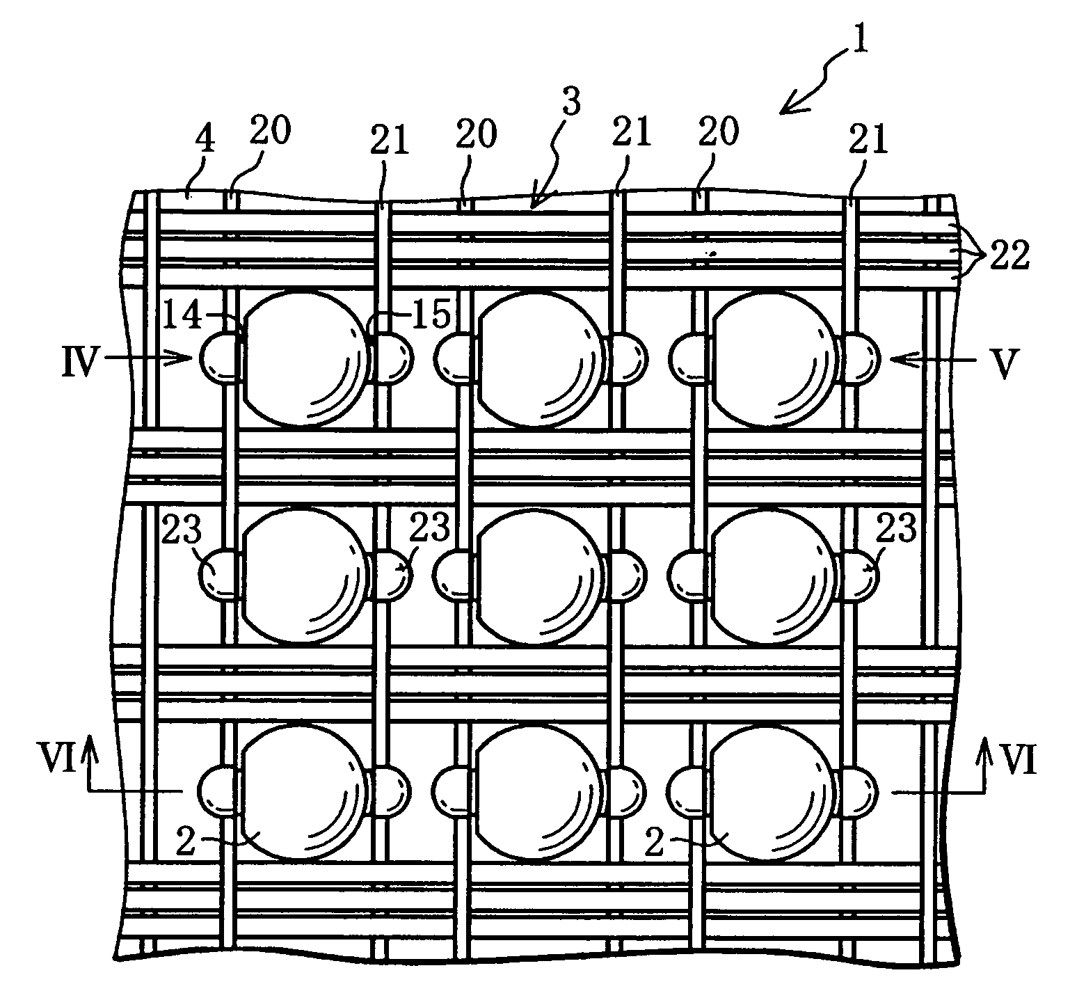
[0077]First, the solar battery element shown in FIG. 8(d) is produced. The silicon oxide film 35 is completely removed using the buffer etching solution to produce a solar battery element 2A, and a mesh member 3A is then prepared by weaving positive and negative electrode conductive wires 20A and 21A extending in the columnar direction and tension wires 22 extending in the row direction. Here, the conductive wires 20A and 21A are made of an aluminum line containing 1% to 2% of silicon that is eutectic reactive to silicon and having a diameter of approximately 120 μm. The tension wires 22 are the same as the tension wires in the afore-mentioned embodiment, hence the explanation is omitted.

[0078]A number of solar battery ...

embodiment 2 (see figs.11 and 12)

2) Modified Embodiment 2 (see FIGS. 11 and 12)

[0082]A modified embodiment having a modified sealing member is described hereafter. A light receiving module sheet 1B may be formed with the structure shown in FIG. 11. The light receiving module sheet 1B is provided with a sealing member 4B comprising a flexible cushion layer 46 that houses the solar battery elements 2 and mesh member 3 in an embedded manner and transparent surface layers 45 joined to the top and bottom surfaces of the cushion layer 46. The surface layers 45 are made of a transparent enforced glass plate having a thickness of approximately 2 mm.

[0083]In order to produce the light receiving module sheet 1B, a surface layer 45, an EVA (ethylene vinyl acetate) sheet, a mesh member 3 to which the solar battery elements 2 are joined, an EVA sheet, a surface layer 45 are superimposed in sequence and are heated in a laminate machine while vacuuming. Then, the EVA sheets melt, the EVA melt between the top and bottom surface la...

embodiment 3

3) Modified Embodiment 3

[0089]The light receiving module sheet may be produced by a roll-to-roll technique. When a roll-to-roll technique is used, the mesh member is fixed at both ends in the width-wise direction using heat-resistant resin films such as polyimide films. Sprocket holes are formed in the heat-resistant resin films. The sprockets holes are engaged in sprockets to roll the mesh member in or out.


PUM


Abstract

A light receiving or light emitting modular sheet having a plurality of spherical elements arranged in matrix. It is constituted only of acceptable spherical elements and photoelectric conversion efficiency thereof is enhanced.The light receiving modular sheet (1) comprises a plurality of spherical solar cell elements (2) arranged in matrix, a meshed member (3), and a sheet member (4). Each solar cell element (2) comprises a spherical pn junction (13), and positive and negative electrodes (14, 15) formed oppositely while sandwiching the center of the solar cell element (2) and being connected with respective electrodes of the pn junction (13). The meshed member (3) has a plurality of conductive wires (20, 21) arranged in parallel in order to connect the plurality of spherical solar cell elements (2) in each column electrically in parallel, and insulating tensile wires (22) arranged between the rows of solar cell elements (2) to cross the conductive wires (20, 21) perpendicularly while being woven in a meshed form to secure the plurality of conductive wires (20, 21).

Description

TECHNICAL FIELD[0001]The present invention relates to a light receiving or emitting module sheet and the production method thereof, and relates particularly to a light receiving or emitting module sheet having conductive wires electrically connected to spherical elements and insulating tension wires for fixing the conductive wires in a woven mesh structure.BACKGROUND OF THE RELATED ART[0002]Solar batteries in currently practical use comprise a flat pn junction formed by diffusing impurities in a flat semiconductor wafer. The solar batteries having this structure produce maximum output when light enters the light receiving surface at a right angle. Output decreases as light enters the light receiving surface at smaller angles. These solar batteries have a strong directional pattern. It would be difficult to say that they constantly utilize light in an efficient manner. Furthermore, wafers are produced by slicing a semiconductor crystal ingot and, thus, there are significant processin...

Claims


Application Information

Patent Timeline
Patent Type & Authority Patents(United States)
IPC IPC(8): H01L21/00H01L25/075H01L31/02H01L31/0352H01L31/042H01L31/0465H01L31/05H01L31/068H01L31/18H01L33/34H01L33/46H01L33/48H01L33/54H01L33/62
CPCH01L31/02008H01L31/035281H01L31/042H01L31/068H01L31/1804H01L33/20H01L33/24H01L25/0753H01L31/0508H01L24/45F21K9/00H01L2924/01322H01L33/38H01L33/62H01L2224/45147H01L2924/01015H01L2924/01047H01L2924/01006H01L2924/00014H01L2224/45144Y02E10/547H01L2224/45565H01L2224/45644H01L2224/45124H01L2924/00H01L2924/01014H01L2924/01032H01L2924/0105H01L2224/48H01L2924/0002H01L2224/45015H01L2224/45139H01L2224/4516H01L2924/12036H01L2924/12041H01L2924/12043H01L24/85H01L2924/00011H01L2924/10338H01L2924/10346H01L2924/10252H01L2924/10329H01L2924/10335H01L2924/10337H01L2924/10328Y02P70/50H01L2924/2076H01L2924/2075H01L2924/00015H01L2924/01028H01L2924/013H01L2924/00013H01L2924/01004H01L2924/01049
Inventor NAKATA
Owner SPHELAR POWER
Why Eureka
Try Eureka