Private IP communication network architecture

a communication network and private IP technology, applied in the field of multimedia communication networks, to achieve the effect of enhancing connectivity and scalability of attached communication devices, performance and operational costs and complexities, and reducing complexity

Inactive Publication Date: 2007-05-08
RPX CORP
View PDF16 Cites 77 Cited by
  • Summary
  • Abstract
  • Description
  • Claims
  • Application Information

AI Technical Summary

Benefits of technology

[0015]One advantage of the present invention is to provide a protocol and network architecture that allows communication between new and legacy components via a translation interface module.
[0016]Another advantage of the present invention is to provide a user with a variety of message types that can be optimized according to the type of data being sent, such as voice, video, or data. The distributed network architecture also allows for the creation of a large fault tolerant system that does not incur the performance and operational costs and complexities associated with building a large monolithic system. Much like the differences between Mainframe and local area network (LAN) computer environments. In the distributed network architecture, transmitted data is identified and optimized by pooling data into categorized data packet types allowing decisions to be made on how this data should be handled and exchanged between servers along the various network types, such as a real time packetized network or PSTN network, available to the user. Yet another advantage of the present invention is the natural command and control infrastructure supplied by the packetized network based architecture, namely, enhanced connectivity and scalability for attached communication devices in a carrier grade network. While a packetized network does not guarantee that all the advantages of an IP network will be available by default, ATM is an example. The present invention utilizes the packetized network and IP protocol to provide the ability address other devices without knowing where the device is or how to get to it. Thereby separating network from application. The advantage of the system we are describing is that this feature of IP networks has been sustained throughout the architecture.
[0017]In summary, the foregoing and other objects, advantages and features are achieved with an improved communication network for use in connecting multimedia devices, such as video, voice, data, other telephony devices, and the like to remote access points and associated communication devices attached to those points, such as modems, telephones, video displays, and network interface cards (NICs). Embodiments of the present invention are particularly suitable for use with such telephony devices that are used in a typical local exchange having one or more jacks or sockets designed to accommodate communication devices. For example, a telephone having an RJ type connector that is inserted into the socket or jack in such a way that the telephone is in communication with the network and may selectively dial a second telephony device via the network.
[0018]In a preferred embodiment, the communication network maintains three layers for each connection, more specifically a physical layer, a network layer, and a service layer. The physical layer is created via the existing IP network, such as the Internet, a private IP network, real time IP network, or combination thereof. A network layer generates a connection that is logically assigned via participating network devices, and finally a service layer generates logical connections necessary to run the desired application. By creating three independent layers the communication network is given the advantages of a distributed network along with the advantages of component specialization and optimization associated with the physical, logical, and service layers. In designing the components of this new communication network, the present invention employs, but is not limited to, elements from Q.931 and SS7 as a basis for call control. A structured, scalable architecture is provided through the defined components and their responsibility.
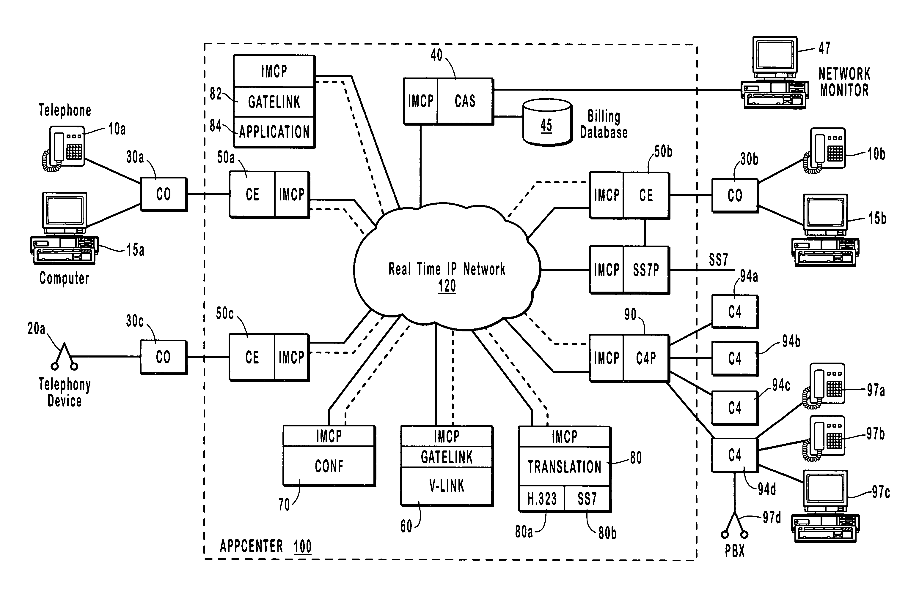
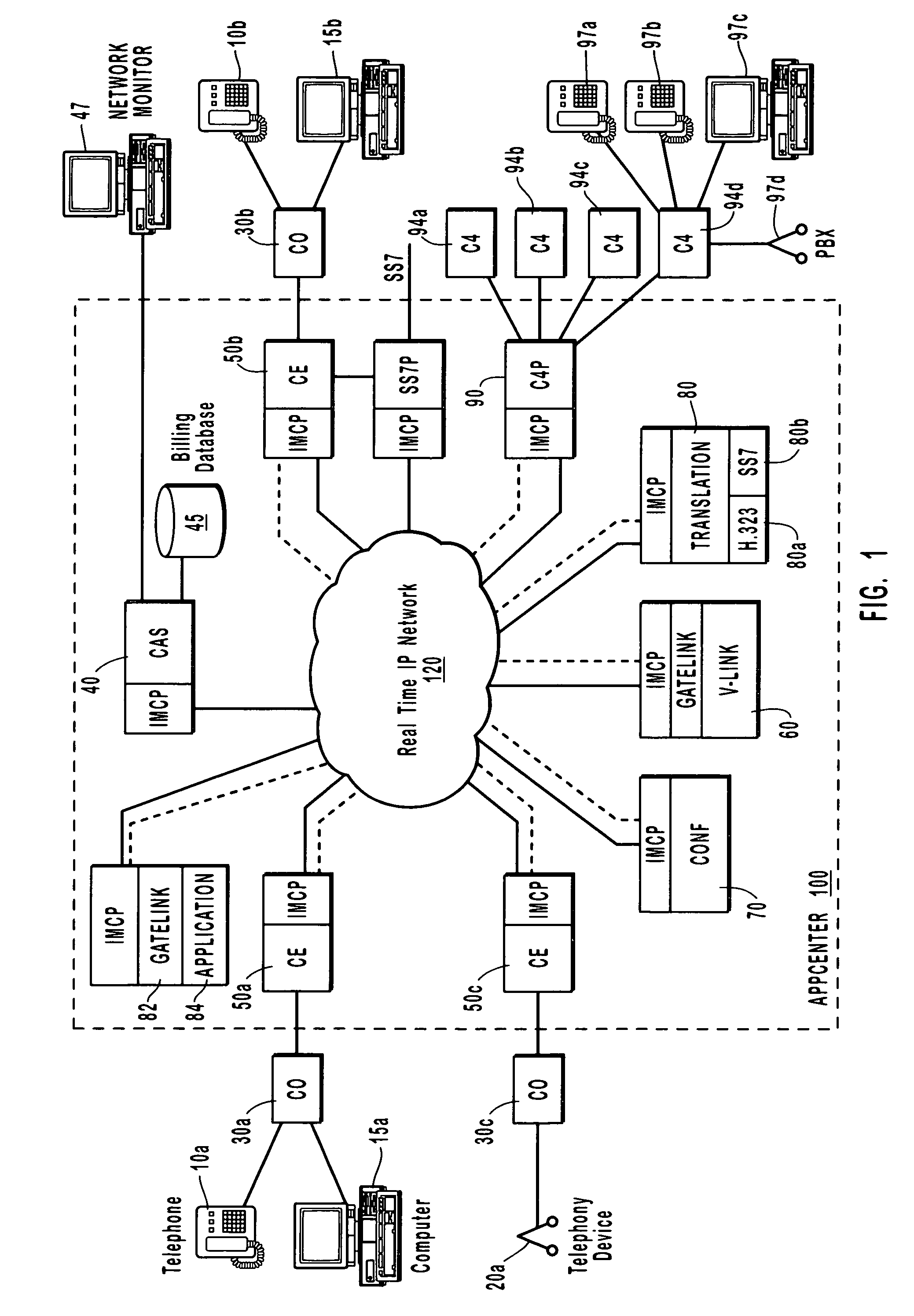
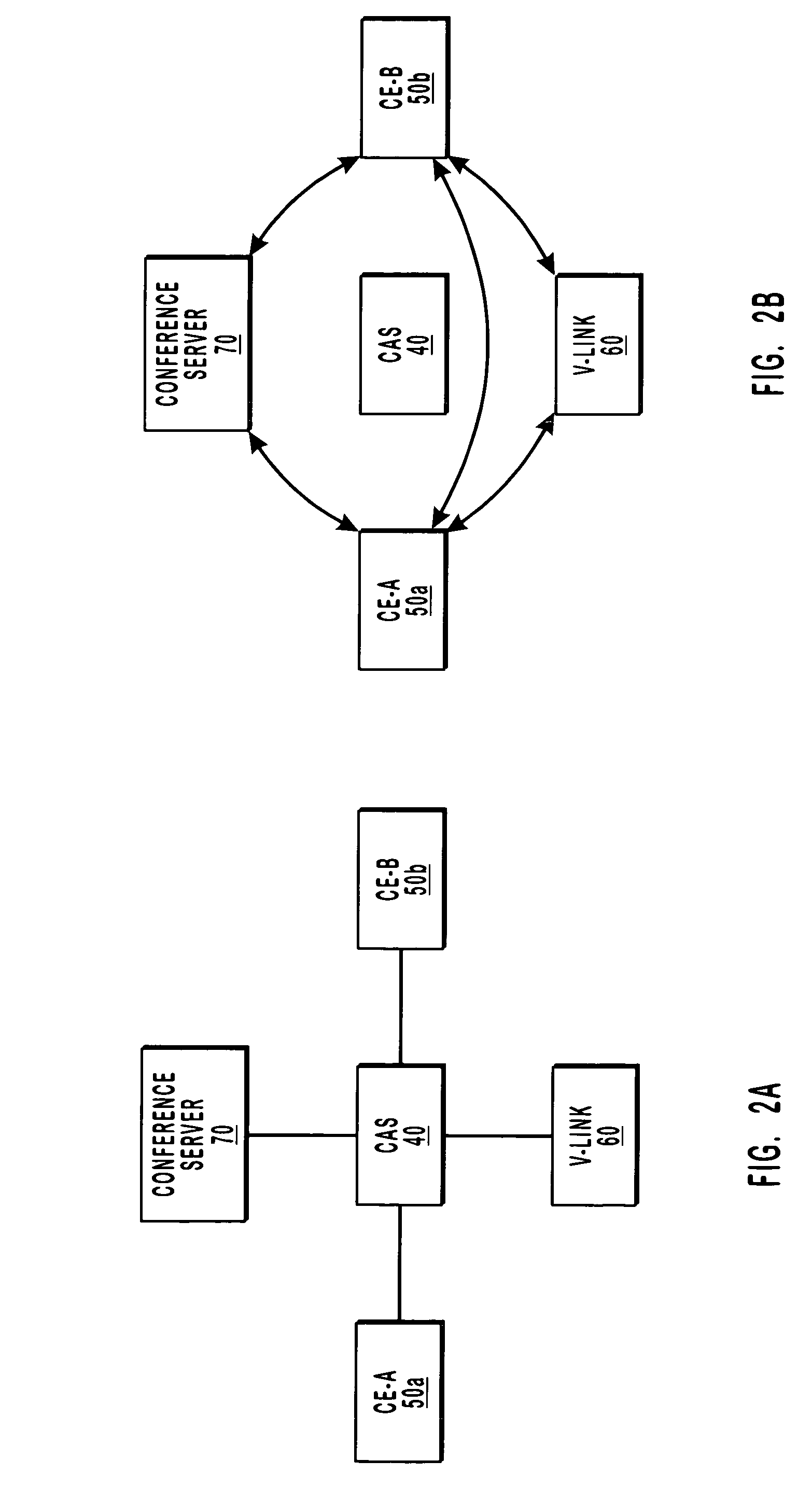
[0019]The network layer comprises at least one central arbitration server (CAS) or gatekeeper, at least one communications engine (CE) or gateway, where both devices are running the Internet Media Control Protocol (IMCP). The CAS is a fault tolerant set of servers that act as gatekeepers on the network. The CAS is responsible for arbitrating resource allocation, passing call control information and collecting billing records. The CE is the network implementation of a voice-over IP (VoIP) gateway. This gateway is built to use the IMCP protocol to take part in the private communication network. The network CE can handle both customer based signaling, such as ISDN-PRI, and carrier signaling, such as SS7. One example of an additional network layer device is a NetLink-IP device (C4). The C4 provides network users with multiple phone lines and a persistent or continuous Internet connection over a single data connection.
[0020]The service layer includes V-Link platform and services and the GateLink API layer. The service layer brings intelligence to the network. V-Link is an example of a VoIP based enhanced service. The network GateLink API offers access to the communication network to third party software developers. The API gives a software abstraction to all the resources on the network. Thereby enabling the creation of application modules, such as a voice portal, a unified message service, and automatic call distribution (ACD) service.

Problems solved by technology

While a packetized network does not guarantee that all the advantages of an IP network will be available by default, ATM is an example.

Method used


Image

  • Private IP communication network architecture
  • Private IP communication network architecture
  • Private IP communication network architecture

Examples


Embodiment Construction

[0031]Reference is first made to FIG. 1, which graphically illustrates an exemplary system or environment in which the present invention may be utilized or implemented. FIG. 1 is intended to be illustrative of potential systems that may utilize the present invention and is not to be construed as limiting. Telephone calling devices 10a, 10b are connected to central office (CO) 30a and 30b, respectively, via PSTN lines. CO 30a and 30b are electrically connected to the IP telephone gateways or communication engine (CE) 50a and 50b via PSTN connections or dedicated communication lines. Other telephony devices 20a are connected to the network via CO 30c that is connected to CE gateway 50c. CE gateway 50a, 50b, and 50c are all part of communication AppCenter 100, which may include, among other things, telephony gatekeeper or central arbitration server (CAS) 40, call detail record (CDR) database 45, network monitor 47, conference server 70, enhanced service platform (V-Link) 60, GateLink s...


PUM


Abstract

A disclosed Internet Linked Network Architecture delivers telecommunication type services across a network utilizing digital technology. The unique breadth and flexibility of telecommunication services offered by the Internet Linked Network Architecture flow directly from the network over which they are delivered and the underlying design principles and architectural decisions employed during its creation. The present invention supports current telecommunication and voice over IP standards and applications. This new network not only replaces the telecommunication network presently in place, but it also offers a more feature rich and cost effective alternative. For example, traditional telecommunication switches are more expensive, less reliable and slower than the faster digital data switches utilized in the present invention. Furthermore, the programmable nature of the digital devices comprising the present invention allows the new network to be built with a scalable and extensible architecture, providing the flexibility necessary to incorporate new or future digital enhancements. The inventive network is designed as a complete replacement for the traditional telecom network. The disclosed architecture allows for this network to connect to traditional networks and allows for an upgrade path. The design is robust and scalable so this network can introduce new features and functionality while preserving the quality of traditional networks.

Description

RELATED APPLICATIONS[0001]This application is a continuation-in-part of application Ser. No. 08 / 599,238, filed Feb. 9, 1996, now abandoned, entitled VOICE INTERNET TRANSMISSION SYSTEM to Wilkes et al. and Ser. No. 08 / 585,628, filed Jan. 16, 1996, now abandoned, entitled FACSIMILE INTERNET TRANSMISSION SYSTEM to Wilkes et al., each of which are incorporated herein by reference.BACKGROUND OF THE INVENTION[0002]1. The Field of the Invention[0003]The present invention relates generally to multimedia communication networks. More particularly, embodiments of the present invention relate to an improved Voice over Internet Protocol (VoIP) network that provides for increased data stream throughput for video / voice / data via a private Internet Protocol (IP) communications network with associated communications components.[0004]2. Description of Related Art[0005]To understand the need for the improved design of the present invention requires a brief overview of the current solutions that need to...

Claims


Application Information

Patent Timeline
Patent Type & Authority Patents(United States)
IPC IPC(8): H04L12/56
CPCH04L12/14H04L12/5695H04L12/66H04L47/15H04L47/2416H04L47/781H04L47/801H04L47/803H04M7/1205H04L47/70
Inventor RADULOVIC, ALEX
Owner RPX CORP
Why Eureka
Try Eureka