Pickup device

a technology of a pick-up device and a slit is applied in the field of pick-up devices, which can solve the problems of large probes, complicated assembling, and limited recording density, and achieve the effects of convenient production, simple structure and suitable mass production

Inactive Publication Date: 2007-05-22
PIONEER CORP +1
View PDF49 Cites 34 Cited by
  • Summary
  • Abstract
  • Description
  • Claims
  • Application Information

AI Technical Summary

Benefits of technology

[0009]It is therefore an object of the present invention to provide a pickup device, used for a dielectric recording / reproducing apparatus, equipped with a recording / reproducing head for recording / reproducing data in / from a dielectric recording medium, having a simple structure, easy to produce, and appropriate for mass production.

Problems solved by technology

However, the pickup is large, which is not appropriate for high-speed reading, and the size of the recording pit is defined by the diffraction limit of light, so that its recording density is limited to 50 G bit / inch2.
However, the recording density is limited to 1 T bit / inch2 due to thermal fluctuation of magnetic recording information and the presence of a Bloch wall in a portion in which a code or sign is reversed or changed, even if patterned media are used considering the above cause.
However, the above-described SNDM has not been specially developed in view of a recording / reproducing apparatus and thus have such a problem that the probe is large or that assembling is complicated.
Moreover, if it has a plurality of probes in order to increase a data transfer rate, the complication increases more.

Method used


Image

  • Pickup device
  • Pickup device
  • Pickup device

Examples


first embodiment

of Pickup Device

[0069]The first embodiment of the pickup device will be explained with reference to FIG. 4. In the first embodiment, the above-described pickup device is equipped with an oscillator and its peripheral circuit elements for recording / reproducing data.

[0070]As shown in FIG. 4, on one end portion of a pickup device 50c, there are disposed an inductor L, which forms a resonance circuit with a capacitance Cs corresponding to the polarization state of the ferroelectric recording medium 1 just under a probe 11a, and an oscillator 13, which oscillates at a resonance frequency formed by the capacitance Cs and the inductor L. This resonance frequency is about 1 GHz, for example.

[0071]A motor of linear type may be used in place of the motor 55a of rotational type. Moreover, FIG. 4 shows the probe 11a of a cantilever type, but a pin or needle-shaped electrode may be used.

second embodiment

of Pickup Device

[0072]The second embodiment of the pickup device will be explained with reference to FIG. 5. In the second embodiment, the above-described pickup device is equipped with an oscillator and its peripheral circuit elements for recording / reproducing data. As shown in FIG. 5, on one end portion of a pickup device 50d, there is disposed the inductor L, which forms a resonance circuit with the capacitance Cs corresponding to the polarization state of the ferroelectric recording medium 1 just under the probe 11a. The oscillator 13, which oscillates at a resonance frequency formed by the capacitance Cs and the inductor L, is disposed on the arm 51. In the pickup device 50d, the probe 11a is placed at one end of the arm 51. The oscillator 13 is placed at the other end of the arm 51. The rotating shaft 54 is located between the probe 11a and the oscillator 13.

[0073]The center of gravity of the pickup device 50d is set at a position near the rotating shaft 54, which improves the...

third embodiment

of Pickup Device

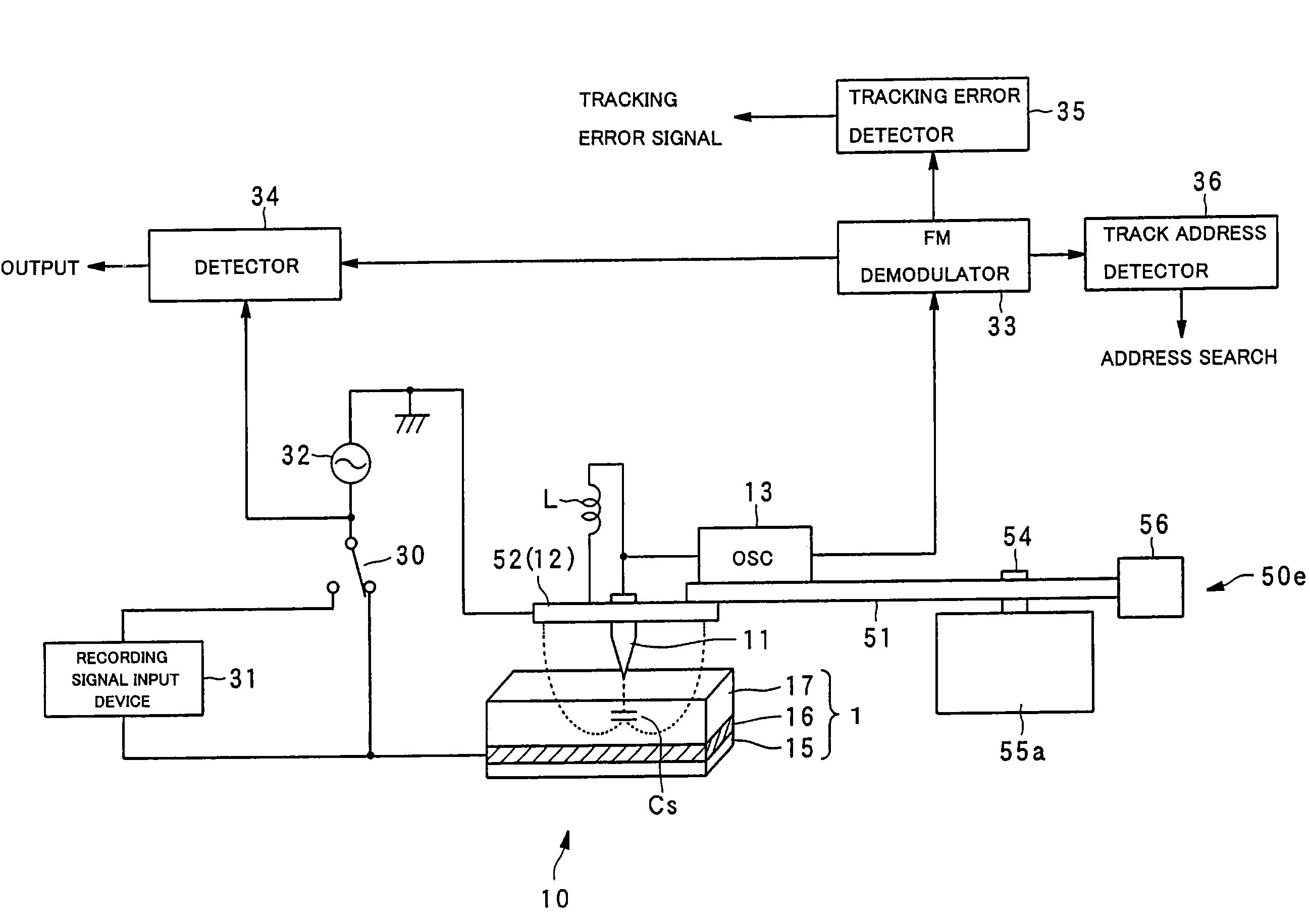
[0074]The third embodiment of the pickup device will be explained with reference to FIG. 6. In the third embodiment, the above-described pickup device is equipped with an oscillator and its peripheral circuit elements for recording / reproducing data, as well as a weight for adjusting the position of the center of gravity of the arm, i.e., a counter weight. As shown in FIG. 6, on one end portion of a pickup device 50e, there are disposed the inductor L, which forms a resonance circuit with the capacitance Cs corresponding to the polarization state of the ferroelectric recording medium 1 just under the probe 11a, and an oscillator 13, which oscillates at a resonance frequency formed by the capacitance Cs and the inductor L. A counter weight 56 is disposed oppositely to the one end portion of the pickup device 50e over the rotating shaft 54. This counter weight 56 is attached after determining its weight and mounting position so that the center of gravity of the pickup d...


PUM

PropertyMeasurementUnit
thicknessaaaaaaaaaa
inner diameteraaaaaaaaaa

Abstract

An example pickup device is provided with: an arm; a gimbal holding device disposed on one end portion of the arm; a gimbal held by the gimbal holding device with a probe set in its center portion; and a motor of rotational type for rotating the arm around a rotating shaft. The probe, which is disposed on one end of the arm, is rotated in the radial direction of a dielectric recording medium by the rotation of the motor, causing accurate and quick tracking control and track access control.

Description

BACKGROUND OF THE INVENTION[0001]1. Field of the Invention[0002]The present invention relates to a pickup device used for a dielectric recording / reproducing apparatus for recording / reproducing information with high density in / from microdomains in a dielectric substance.[0003]2. Description of the Related Art[0004]As high-density, large-capacity recording / reproducing apparatuses of randomly accessible type, there are known an optical disk apparatus and a hard disc drive (HDD) apparatus. Moreover, a recording / reproducing technique using a scanning nonlinear dielectric microscopy (SNDM) for the nanoscale analysis of a dielectric (ferroelectric) material has been recently proposed by the inventors of the present invention.[0005]In optical recording, which uses an optical pickup with a laser as a light source, data is recorded by forming pits that are concavo-convex on a disk surface or by forming the crystal phase of a phase shift medium, and the data is reproduced by using the differen...

Claims


Application Information

Patent Timeline
Patent Type & Authority Patents(United States)
IPC IPC(8): G11B7/00G01Q10/00G01Q60/00G01Q60/40G01Q80/00G11B9/00G11B9/02G11B9/06G11B9/07G11B9/14G11B11/00G11B11/08
CPCB82Y10/00G11B9/02G11B9/06G11B9/07G11B9/14G11B9/1409G11B9/1418G11B9/149G11B11/007G11B11/08G11B9/075
Inventor ONOE, ATSUSHICHO, YASUO
Owner PIONEER CORP
Why Eureka
Try Eureka