
Two-stroke cycle engine

a two-stroke cycle engine and cycle technology, applied in the direction of combustion air/fuel air treatment, machines/engines, fuel air intakes, etc., can solve the problems of fuel wastage, increased cost, and the airflow supplied through the supply passage during scavenging not being controlled to conform to the operating state of the engine, so as to reduce the quantity of fuel-air mixture, reduce fuel wastage, and simple shape

Inactive Publication Date: 2007-06-05
MITSUBISHI HEAVY IND MEIKI ENGINES CO LTD
View PDF24 Cites 4 Cited by
  • Summary
  • Abstract
  • Description
  • Claims
  • Application Information

AI Technical Summary

Benefits of technology

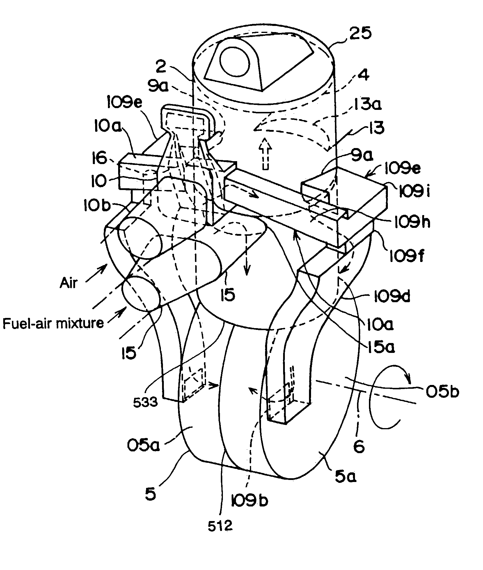
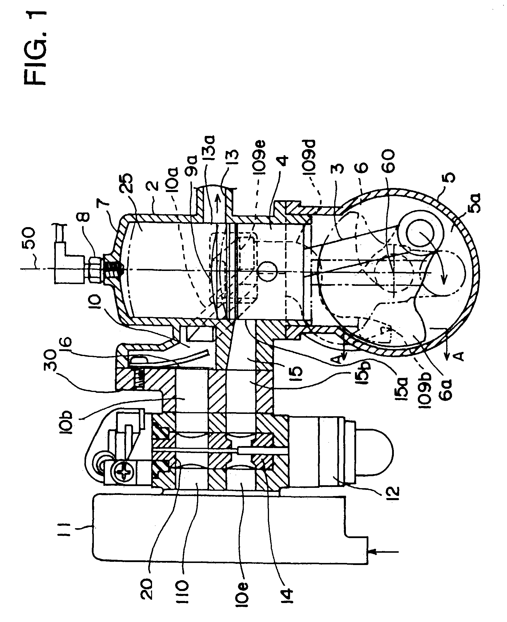
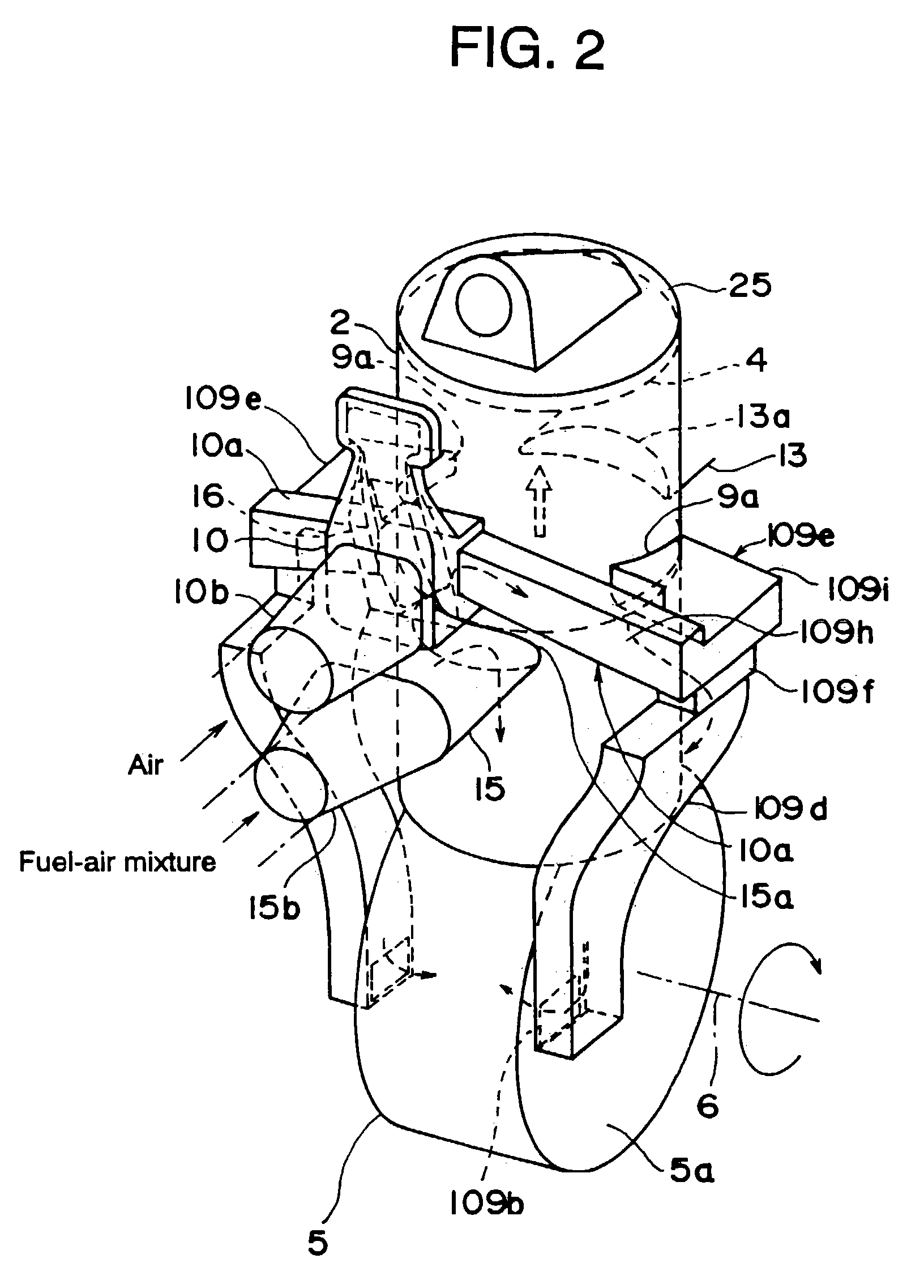
[0148](1) With the inventions disclosed initially, all scavenger passages and air passages are formed inside the crankcase and the cylinder. This obviates the need for external pipes to serve as air passages as well as their mounting hardware. Fewer parts and assembly processes are required, and the engine can be made lighter and smaller.
[0149]The scavenger passage is formed of two passages, one created by walls in the crankcase and the other by similar walls in the cylinder. The result is a long scavenger passage which can be filled with air for the scavenging operation. Since the fuel-air mixture is supplied only after the crankcase has been thoroughly scavenged by this air, no fuel is lost through the exhaust port, and fuel wastage is minimized.
[0150]If configured as preferred, the outlet of the scavenger passage on the side of the crankcase opens into the crank chamber. The gap between the side of the crankcase and the crank web is reduced, and a disk valve is formed by the outlet on the crankcase and the crank web. This controls the velocity of the air forced in through the scavenging port and reduces the quantity of fuel-air mixture which becomes trapped in the exhaust gas stream.
[0151]If configured in accordance with another preferred embodiment, the branching air passage and the branching passage to the scavenging port in the cylinder are both enclosed by walls that run parallel in the same direction. This allows the sliding die for the scavenger passage to be one piece in the process of casting the cylinder. The die can have a simpler shape and will be cheaper to produce.
[0152]If the engine is configured according to other preferred embodiments, a valve controls the air flow supplied to the combustion chamber via the scavenging port of the engine. This air control valve is interlocked with the fuel-mixture control valve through a cam mechanism which rotates with the fuel-mixture valve. This allows the opening and closing of the air and fuel control valves to be controlled in relation to each other.
[0153]Thus when the engine is operating under a light load, the air control valve can be fully closed or opened only slightly so that the fuel mixture is richer and stable combustion can be maintained. When the engine is operating under a heavier load, the air control valve can be opened or closed proportionally with the fuel mixture control valve to produce a thinner mixture. We can thus provide an air-layer-type scavenging two-stroke engine in which the overall richness of the mixture can be kept at the appropriate concentration, the rate of fuel consumption is reduced, and the quantity of pollutants in the exhaust gas is lowered.

Problems solved by technology

This is the primary cause of the large component of THC (total hydrocarbons) in the exhaust, and it results in the wastage of fuel.
The design thus required a large number of parts and assembly processes, both of which drove the cost up.
However, in the prior art design proposed in the Japanese Patent Publication (Kokai) 7-139358, the airflow supplied via the supply passages during scavenging is not controlled to conform to the operating state of the engine.
Under light load conditions, then, such as when the engine is idling, too much air is supplied; and it would be difficult to stabilize combustion by limiting the quantity of air admitted to produce a rich mixture.
Similarly, it would be difficult to maintain a thin mixture under heavy load conditions in order to reduce the pollutants in the exhaust gas and lower the fuel consumption.
This causes the throttle to open more, suddenly increasing the speed of the engine.
The delay in the fuel supply allows the excessively rich fuel mixture to be thinned out by radically increasing the quantity of preceding air.
The concentration of the fuel will decrease and proper combustion will no longer be possible.
Problems with acceleration or engine cut-off may result.
However, in the inventions disclosed in the Japanese Patent Publications 7-139358, 10-252565 and 9-125966, no means are provided to control the ratio of air flow to air-fuel mixture flow during normal operation so as to prevent an excessive quantity of air from being supplied when the engine suddenly accelerates as was described above.
Furthermore, when this sort of two-stroke cycle engine is used in a lawnmower, in many cases it must operate while mounted obliquely.
When the position of the engine changes, this fuel is sucked in suddenly, resulting in combustion problems due to excess fuel in the engine.
However, the prior art techniques did not offer any method to counteract problems arising from the engine being operated while mounted obliquely.
This complicated the casting work and increased the number of casting processes.
Also, because it required combining a number of dies, the probability of a defective cast due to slippage of a die increased.
These designs, then, suffer from the same problems as were just described.
When the engine is operated in an oblique position, this fuel will return to the scavenger passage and result in defective combustion.
These designs thus suffer from the same problem which is described above.
As a result, after the fuel-air mixture forced into the combustion chamber from the portion of the scavenger passage closer to the exhaust port reaches the top of the combustion chamber, it is liable to be caught in the flow of combustion gases travelling toward the exhaust port.
This will increase the quantity of the THC (total hydrocarbons) which are exhausted and the quantity of fuel which is wasted.
The crankcase and cylinder, which are generally made of cast aluminum, must assume a complicated shape, so that their casting requires many processes.
In the design in the Japanese Patent Publication (Kokai) 58-5424, however, the inventors limited their improvement to giving the two long primary and auxiliary scavenger passages in the crankcase and cylinder a smooth contour and so reducing the resistance of the two channels.
However, this design requires two air cleaners, so the configuration is complicated and large, which drives up the equipment cost.
For this reason it would be extremely difficult to completely shut off the preceding air, that is, the air which flows into the air supply passage, at the outlet stage of the air cleaner during start-up.
And since it is difficult to achieve a high negative pressure as well, the start-up characteristics are unavoidably poor.
Also, the rocking diameter of the operating lever is considerable, which makes it difficult to operate and so affects the ease of operation.

Method used


Image

  • Two-stroke cycle engine
  • Two-stroke cycle engine
  • Two-stroke cycle engine

Examples


first embodiment

[0243]FIGS. 6 through 8 show the second preferred embodiment of a preceding air layer-type scavenging two-stroke engine according to this invention. In this embodiment, the air control valve 20 of the two-stroke engine of the first embodiment is replaced by a modified valve 20 which has the following improvements.

[0244]In FIGS. 6 through 8, 11 is the air cleaner, 12 the carburetor, 10e the air passage in carburetor 12, and 14 the fuel mixture control valve of carburetor 12. 15 and 15b are the fuel mixture passages, and 15a is the supply inlet for the fuel mixture on cylinder 2.

[0245]20 is the air control valve. 45 is an air pipe connecting the air passage 10e of the air cleaner 11 to a separate outlet. 35 is the air supply pipe in the insulator attached to the cylinder 2. 36 is a joint pipe for intake air. It is attached to air supply pipe 35 in the insulator and connected to the outlet of the air passage 110.

[0246]As is shown in FIG. 7, the scavenging air, which is conducted throug...

second embodiment

[0263]Control lever 124 is fixed to the rotary stem of mixture control valve 14 on the carburetor 12. On the end of control lever 124, in contrast to the configuration of the second embodiment, is portion 127c, which is bent upward. This forms internal cam 127a, whose horizontal cross section is fan-shaped. The internal cam 127 is interlocked with cam follower 38 of air valve 37 so that it opens and closes that air valve. The internal cam 127a is installed so that it opens air valve 37 through the action of cam follower 38 in the direction opposite the air flow, i.e., in the direction in which it exerts pressure on compressive spring 41.

[0264]Other aspects of the configuration and operation of this engine are identical to corresponding aspects of the second embodiment, and have been given the same numbers.

[0265]FIGS. 12 through 18 show the fourth preferred embodiment of this invention. In this embodiment, the respective supply systems for the preceding air and the fuel mixture have ...

fourth embodiment

[0283]In the fourth embodiment, the air passage 10b and fuel-mixture passage 15 are connected either by small-diameter connecting passages 43 and 44 in insulator gasket 41 and carburetor gasket 42 or by slits 47 and 51, which are cut into insulator 30. When the engine is idling, then, the fuel-air mixture in fuel passage 15 goes through either small-diameter connecting passages 43 and 44 or slits 47 and 51 into air passage 10b and air supply chamber 10.

[0284]Thus when there is too much air in air passage 10b during sudden acceleration, fuel-air mixture can be added to the air flowing through air passage 10b. This prevents the new air being supplied to combustion chamber 25 via scavenging port 9a from causing there to be excess air in the chamber. It thus also prevents the fuel concentration from becoming too thin during sudden acceleration and so improves the engine's acceleration characteristics.

[0285]When the engine is running at a high speed, the throttle is opened more, and the ...


PUM


Abstract

This invention concerns a two-stroke cycle engine, more specially it concerns a two-stroke cycle engine using a preceding air-layer for scavenging. It has a scavenger passage connected to a branching scavenger passage opened to said scavenging port. The engine has a connecting passage to link the air passage and the fuel passages so that negative pressure in the air passage forces the fuel-air mixture in the fuel passage into said air passage. Further, the engine according to this invention has a removable guide with a surface forming a curved smooth channel which is attachable to the scavenger passage in the crankcase from the mounting surface, and forms a portion of said scavenger passage with the curved channel. The blow-up angle of the scavenger passage varies along the circumferential direction of the cylinder. The crankcase is configured in such a way that the front and rear portions, which are separated by a block, and a scavenger passage is provided inside both said front and rear portions of said crankcase, and the cylinder. The air cleaner has two air passages running from it in parallel, the first one is connected to said air passage, and the second one is connected to the air inlet of the carburetor to provide air for the fuel passage, and a choke valve on the air cleaner is provided to open and close both of the first and second air passages.

Description

CROSS REFERENCE TO RELATED APPLICATIONS[0001]This application is a division of application Ser. No. 10 / 338,727 filed Jan. 9, 2003, now U.S. Pat. No. 6,729,276, which is a division of application Ser. No. 10 / 152,035 filed May 22, 2002, now U.S. Pat. No. 6,564,761, which is a division of application Ser. No. 09 / 832,802, filed Apr. 12, 2001, now U.S. Pat. No. 6,408,805, which in turn is a division of application Ser. No. 09 / 558,596, filed Apr. 26, 2000, now U.S. Pat. No. 6,257,179.BACKGROUND OF THE INVENTION[0002]1. Field of the Invention[0003]This invention concerns a two-stroke cycle engine which uses a layer of scavenging air pressurizing the crankcase. More specifically, it concerns a small two-stroke cycle engine using a preceding air-layer for scavenging, which drives a layer of scavenging air in advance of the fuel-air mixture.[0004]2. Description of the Related Art[0005]Two-stroke cycle engines belonging to the prior art take advantage of the fact that a negative pressure is cr...

Claims


Application Information

Patent Timeline
IPC IPC(8): F02B33/04F02B25/14F02B25/22F02B75/02F02D9/02F02M17/04F02M23/03F02M35/10F02M35/108
CPCF02B25/14F02B25/22F02B33/04F02F7/0036F02M17/04F02M23/03F02M35/10078F02M35/1017F02M35/1019F02M35/10196F02M35/10275F02M35/108F02B2075/025F02D2009/0279F05C2201/021Y02T10/146Y02T10/12
Inventor UENOYAMA, KAZUYUKIKOBAYASHI, YOSHIOKUDOU, KAZUNORI
Owner MITSUBISHI HEAVY IND MEIKI ENGINES CO LTD
Learn More