
Process for producing low-molecular olefins by pyrolysis of hydrocarbons

a technology of hydrocarbon pyrolysis and hydrocarbons, which is applied in the field of petrochemical industry, can solve the problems of increasing the yield of less valuable acetylene, overheating the cracking tube, and reducing the productivity of the pyrolysis plant, and achieves the effect of reducing the energy consumption of process conducting

Inactive Publication Date: 2007-06-19
COOLBROOK
View PDF1 Cites 18 Cited by
  • Summary
  • Abstract
  • Description
  • Claims
  • Application Information

AI Technical Summary

Benefits of technology

The invention is a process for producing low-molecular olefins by thermal pyrolysis of hydrocarbons. The process has several technical effects: 1. The heat is not transferred into the reaction zone through the boundary of the reaction zone. This means that the heating of the hydrocarbon feedstock does not need to be done in a separate heat exchanger. 2. The amount of added steam-diluent per mass of hydrocarbon feedstock does not exceed the limits accepted in existing pyrolysis plants. 3. The process is performed in a reactor with an annular work cavity, which allows for a high heat-generation per unit volume. 4. The reactor is designed with a single-stage design, which makes it easier to fabricate and reduces energy consumption. 5. The process uses a gas-turbine engine as a drive for the reactor, which allows for effective utilization of the heat of the exhaust gas. 6. The process is carried out with a short preheating time and a low temperature rise of the process stream. 7. The process is performed with a high degree of safety and control.

Problems solved by technology

It is undesirable to increase the pyrolysis temperature above 950–1000° C., because this accelerates sharply coke formation and causes increase in yield of less valuable acetylene yield at the expense of ethylene.
Coke deposits increase a pressure drop through cracking tubes and deteriorate a proper heat transfer into reaction zone, resulting in overheating the cracking tubes, decrease in productivity of pyrolysis plant and decrease in yields of low-molecular olefins.
a. it is necessary to transfer a large amount of heat into the reaction zone through the cracking tube walls. Because of large heat flows the temperature of the cracking tube wall much exceeds the temperature of a process stream causing an intensive coke formation and decrease in desired products yield. It is impossible to decrease the pressure in the zone of pyrolysis because of the necessity to provide a high rate of feedstock flow through this zone required by conditions of heat transfer;
b. the rate of feedstock heating through the cracking tube is insufficient. So an initial amount of desired olefins formed at relatively low temperatures and carried further by feedstock flow through more and more intensively heated zones resides an excess time under conditions, when secondary reactions proceed with grate intensity. This disadvantage becomes greatly evident in pyrolysis of wide petroleum fractions, such as naphtha or gas oil, which contain both easy cracked high-molecular hydrocarbons and low-molecular hydrocarbons cracked under higher temperatures.
Because of this the energy expenses per unit of produced ethylene are excessively high and can not be essentially decreased.
Thus this apparatus noncompetitive at current interrelation of energy costs with olefin costs.
Unfortunately, high severity of destruction process, typical for pyrolysis of hydrocarbons in tubular furnaces, in this apparatus is impossible.
Difficulties appearing in development of this apparatus are so heavy that such apparatus has not been fabricated.
Thus all known methods of low-molecular olefins production by thermal pyrolysis of hydrocarbons when a heat is not transferred into zone of reaction through boundary of this zone are not suitable for commercial using.

Method used


Image

  • Process for producing low-molecular olefins by pyrolysis of hydrocarbons
  • Process for producing low-molecular olefins by pyrolysis of hydrocarbons
  • Process for producing low-molecular olefins by pyrolysis of hydrocarbons

Examples


Embodiment Construction

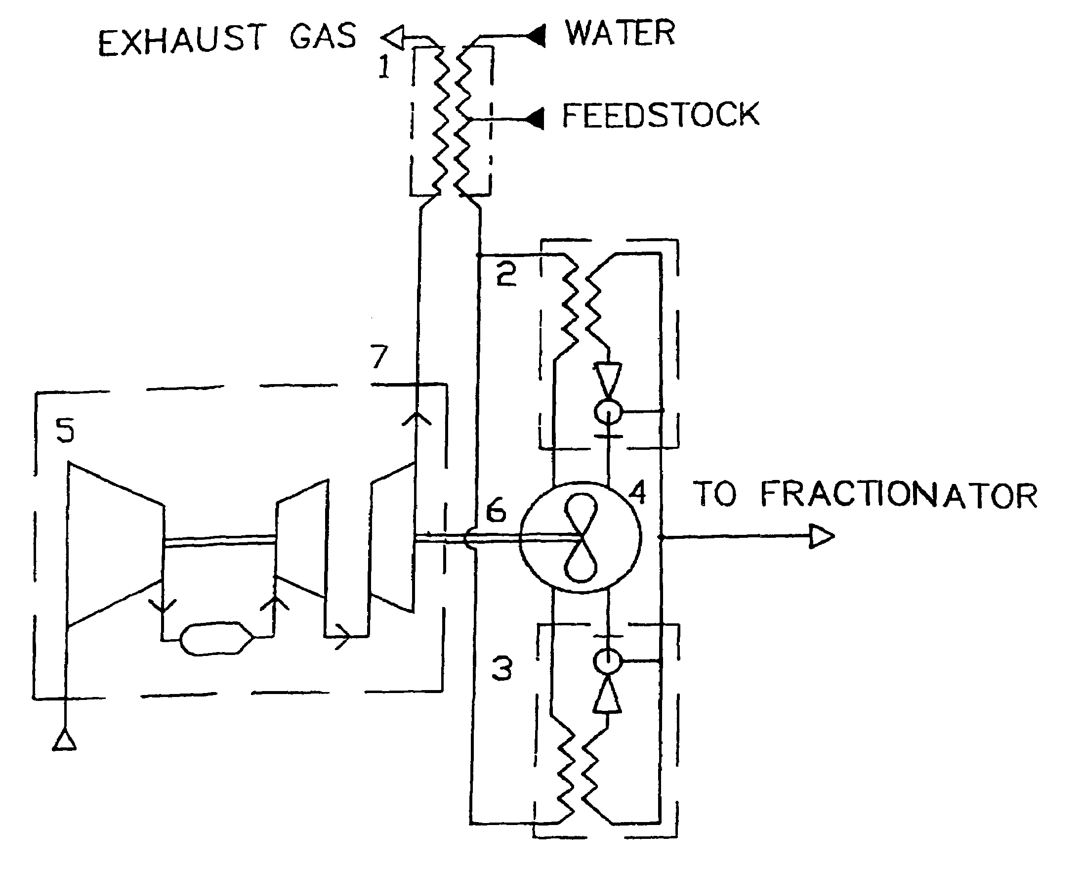
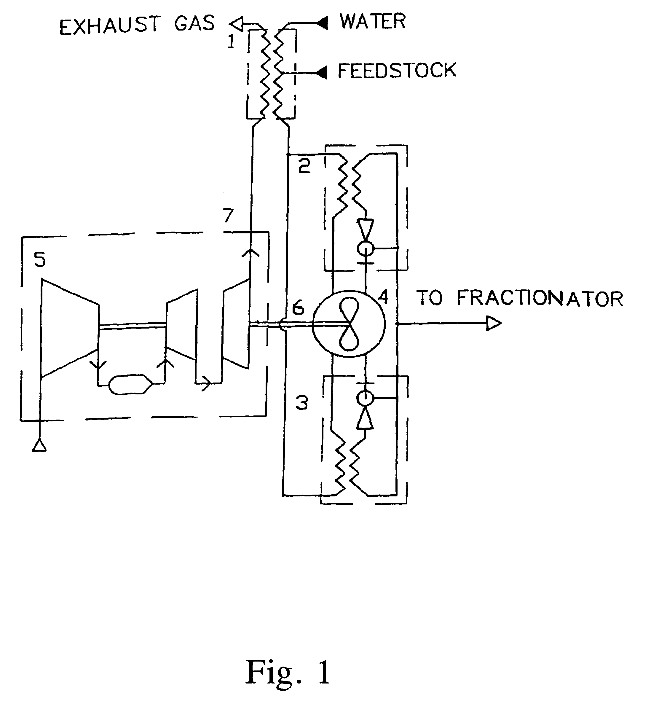
[0055]The installation (FIG. 1) for realization of the process includes preheater 1, apparatuses 2 and 3 for quenching of product stream, reactor 4, gas-turbine engine 5 connected with reactor 4 by shaft 6, and with the preheater 1 by exhaust pipe 7.

[0056]Preheating a feedstock and steam-diluent in the first stage is carried out in the preheater 1. The hydrocarbon feed form outside source (not shown in drawings) is conveyed by pressure into the preheater 1 configured as a shell-tube heat exchanger. The exhaust gas from the gas-turbine engine 5 is discharged into the intertubular space of this heat exchanger. From an outside source (not shown in drawings) water is conveyed by pressure into the preheater where the water it is evaporated, and resulting steam-diluent is mixed with the hydrocarbon feed.

[0057]Preheating a feedstock and steam-diluent in the second stage is carried out in the apparatuses 2 and 3 for quenching of product stream by utilization of heat of product stream leavin...


PUM

PropertyMeasurementUnit
outlet temperatureaaaaaaaaaa
temperatureaaaaaaaaaa
pressureaaaaaaaaaa

Abstract

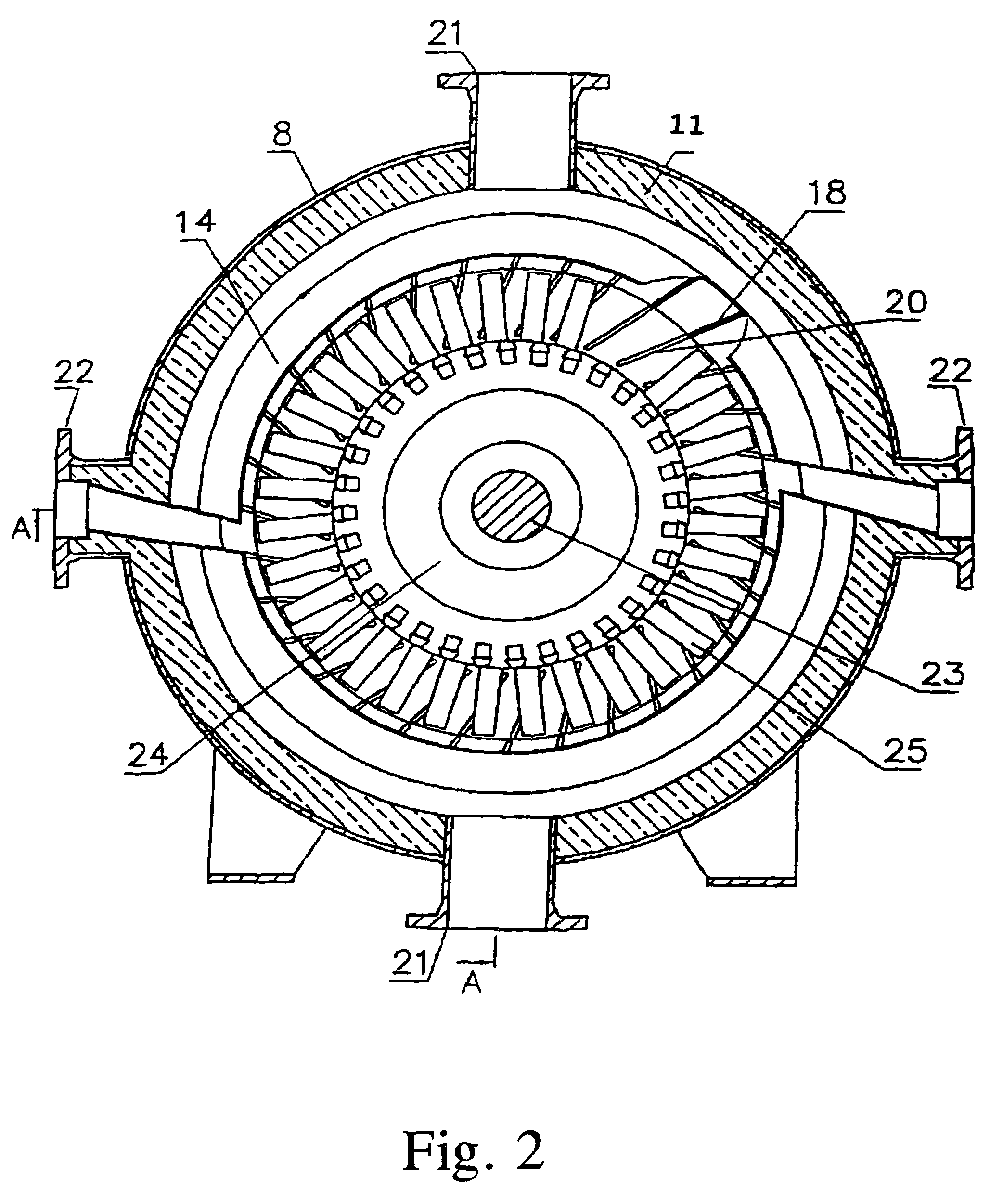
Process for producing low-molecular olefins by pyrolysis of hydrocarbons comprising mixing of feedstock with steam-diluent, preheating the resulting mixture, rapid heating the said mixture up to pyrolysis temperature and maintaining this temperature inside reactor during residence time, quenching product stream and subsequent fractionation of products. The reactor has an annular work cavity where stationary blades and rotatable work blades are located. A ring vortex flow is created and maintained in the work cavity when the work blades are rotated. A heat needed for pyrolysis is generated due to hydrodynamic drag of rotated work blades. Heating the mixture up to pyrolysis temperature is performed by mixing with hot process stream recirculated in the work cavity for a negligible time in comparison with the residence time. The process enables increase of the low-molecular olefins yield.

Description

CROSS-REFERENCE TO RELATED APPLICATIONS[0001]This application is a continuation of Ser. No. 09 / 649,431 filed Aug. 25, 2000 now abandoned.FIELD OF THE INVENTION[0002]The invention relates to the petrochemical industry specifically to the production of low-molecular olefins by thermal cracking (pyrolysis) of hydrocarbons.BACKGROUND OF THE INVENTION[0003]At present a thermal pyrolysis of hydrocarbons is the basic process of commercial production of low-molecular olefins—ethylene and propylene. As a feedstock there are used hydrocarbons which molecule has two or more atoms of carbon. In industry there are generally used gases of petroleum refining, as well as naphtha and gas oil fractions.[0004]In generally accepted technology a feedstock mixed with steam and preheated, is supplied into a cracking tube located inside radiant section of pyrolysis furnace, wherein the mixture is rapidly heated. Pyrolysis reactions proceed with large absorption of heat. A product stream having the outlet t...

Claims


Application Information

Patent Timeline
Patent Type & Authority Patents(United States)
IPC IPC(8): C07C4/04C10G9/00F28D7/10C10G9/04C10G9/16C10G9/18C10G9/36
CPCC10G9/00C10G9/04C10G9/18C10G9/36B01F5/043B01F5/102B01F15/065B01J19/0066B01J19/18B01J6/008B01J2219/00103B01J2219/00123B01J2219/00155B01J2219/00159B01J2219/00162B01J2219/00166B01J2219/00189B01F25/31243B01F25/51B01F35/92
Inventor BUSHUEV, VLADIMIR ANDREEVICH
Owner COOLBROOK
Learn More