Method for characterizing optical systems using holographic reticles

a technology of optical systems and holographic reticles, applied in the field of characterizing optical systems, can solve the problems of difficult to obtain the performance of an optical system or projection optics without time-consuming techniques, noise is introduced into data, focus errors, scan errors and temporal variations of optical system parameters during measurement, etc., to achieve rapid acquisition of data, rapid characterization of optical systems, and rapid acquisition

Inactive Publication Date: 2007-07-10
ASML US LLC +1
View PDF82 Cites 13 Cited by
  • Summary
  • Abstract
  • Description
  • Claims
  • Application Information

AI Technical Summary

Benefits of technology

[0011]Accordingly, it is an advantage of the present invention that an optical system is characterized quickly and in a single exposure or imaging operation.
[0012]It is an advantage of the present invention that it results in a rapid acquisition of data required for characterization of an optical system.
[0013]It is another advantage of the present invention that it results in rapid acquisition of data desensitized to the focus, scan, and temporal errors associated with prior techniques.
[0014]It is an advantage of the present invention that reticle writing errors are reduced or eliminated by holographically patterning the test reticle, as compared to e-beam or laser reticle writing tools.
[0015]It is an advantage of the present invention that holographically patterned reticles can print linewidths that are much smaller than current reticle writing tools.
[0016]It is an advantage of the present invention that pitch uniformity for periodic gratings can be tightly controlled by holographically patterning test reticles. For example, chirped or continuously variable pitch patterns can be produced with great accuracy. This affords the probing of optical system performance over a precisely-controlled continuum of linesizes, line orientations, and pattern pitches.

Problems solved by technology

Often, the performance of an optical system or projection optics is difficult to obtain without time consuming techniques.
Consequently, focus errors, scan errors and temporal variations to the optical system parameters during the measurement are compounded.
In the case of scan and focus errors, noise is introduced into the data.
In the case of temporal variations, valid data are unrecoverable.
Consequently, quantization errors result from estimation of data values that lie between adjacent samples.

Method used


Image

  • Method for characterizing optical systems using holographic reticles
  • Method for characterizing optical systems using holographic reticles
  • Method for characterizing optical systems using holographic reticles

Examples


Embodiment Construction

1. Characterizing Optical Systems

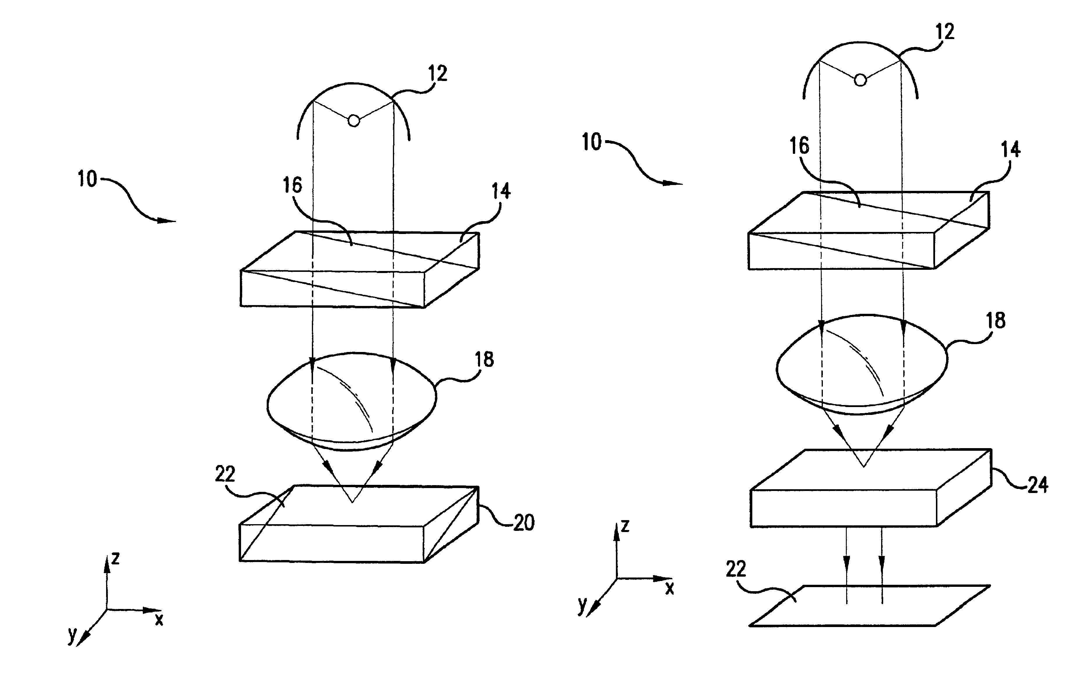
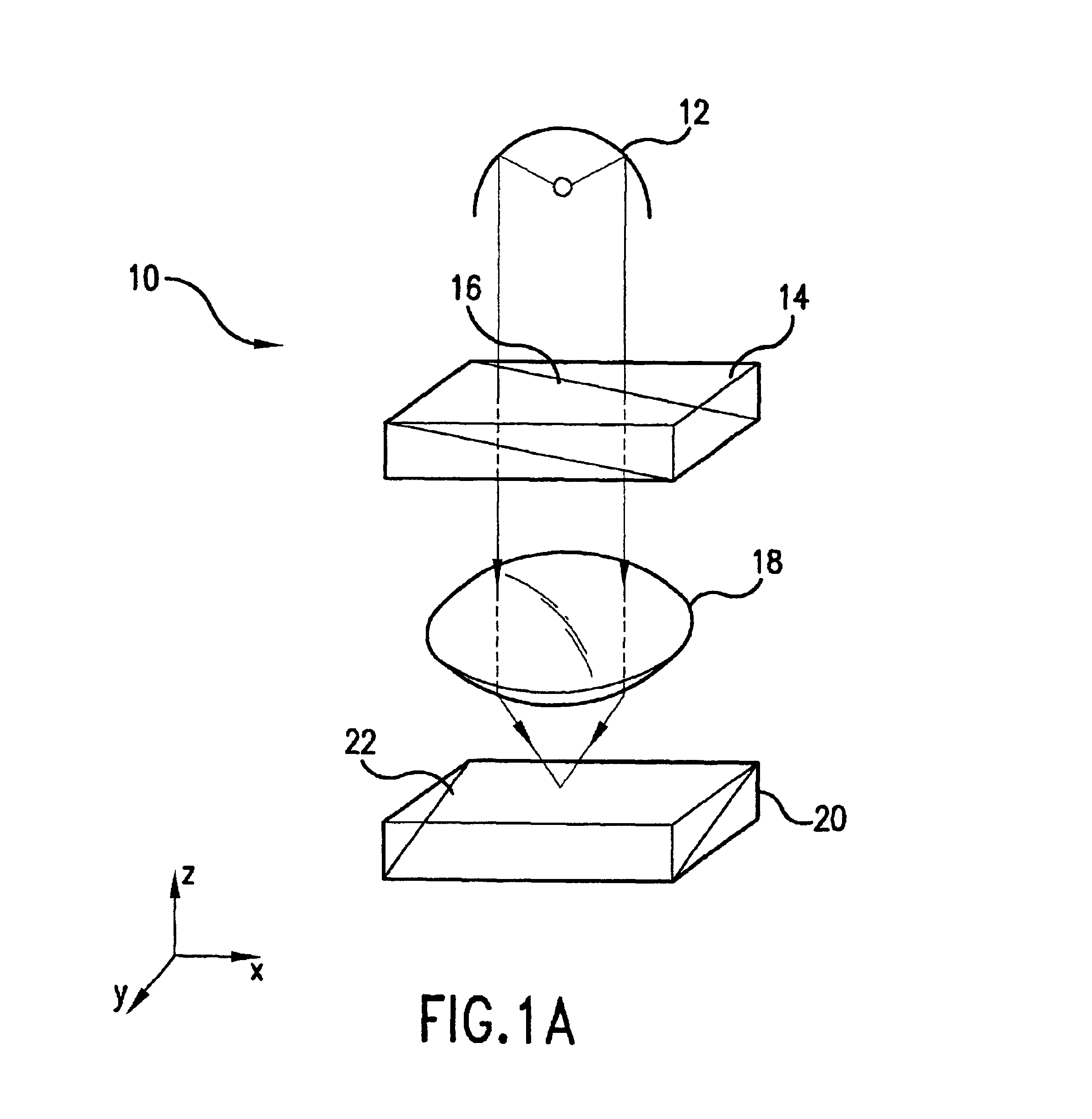
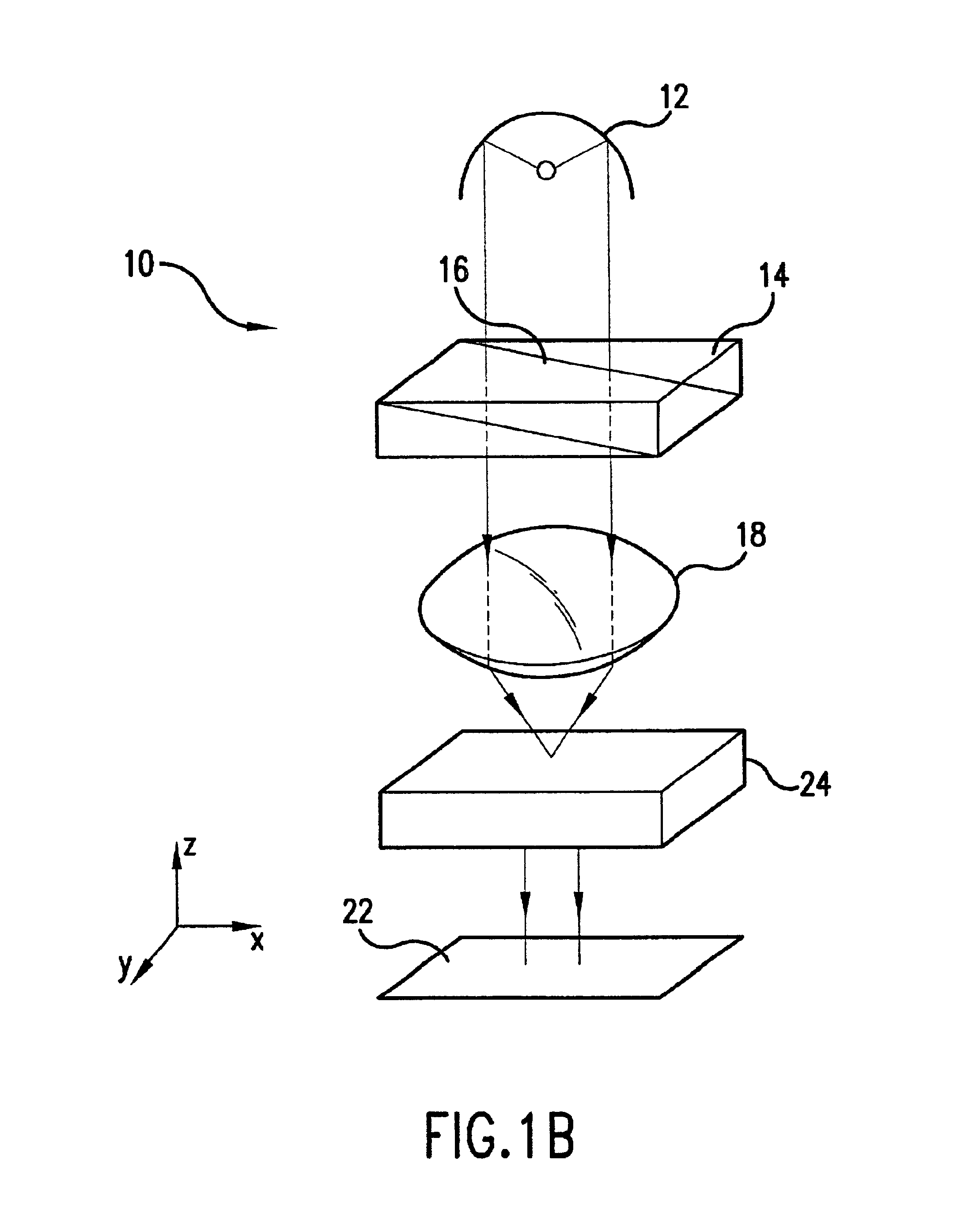
[0072]FIG. 1A schematically illustrates the present invention. A photolithographic system 10 is generally illustrated. An illumination source 12 is used to project the image of a reticle 16 within a reticle or object space or volume 14 onto a photosensitive substrate 22 within a photosensitive substrate or image space 20 through optical system or projection optics 18. The reticle 16 is positioned within a plane that is oblique with respect to the photosensitive substrate 22. The reticle 16 and the photosensitive substrate 22 can be tilted in a variety of different ways. Preferably, the positioning of the reticle 16 or the wafer 22 is such that either the reticle 16 or wafer 22 extends through the object volume or depth of focus of the optical system or projection optics 18. The imaging data recorded by the photosensitive substrate 22 provides information permitting the characterization of the optical system or projection optics 18. Imaging characteri...


PUM

PropertyMeasurementUnit
width w1aaaaaaaaaa
width w1aaaaaaaaaa
lengthaaaaaaaaaa

Abstract

Characterization of an optical system is quickly and easily obtained in a single acquisition step by obtaining image data within a volume of image space. A reticle and image plane are positioned obliquely with respect to each other such that a reticle having a plurality of feature sets thereon, including periodic patterns or gratings, is imaged in a volume of space, including the depth of focus. Metrology tools are used to analyze the detected or recorded image in the volume of space through the depth of focus in a single step or exposure to determine the imaging characteristics of an optical system. Focus, field curvature, astigmatism, spherical, coma, and / or focal plane deviations can be determined. The present invention is particularly applicable to semiconductor manufacturing and photolithographic techniques used therein, and is able to quickly characterize an optical system in a single exposure with dramatically increased data quality and continuous coverage of the full parameter space. In embodiments, the test reticle is holographically generated by interfering two or more beams of optical radiation. The resulting interference pattern is recorded on a reticle and used for testing the optical system. The geometry of the holographic interference pattern is tightly controlled by the properties of the interfering beams and is therefore more accurate than conventional reticle writing techniques.

Description

CROSS-REFERENCE TO RELATED APPLICATIONS[0001]This application is a continuation-in-part of U.S. application Ser. No. 09 / 339,506, filed on Jun. 24, 1999, which is incorporated by reference herein in its entirety. This application also claims the benefit of U.S. Provisional Application No. 60 / 219,187, filed Jul. 19, 2000, which is incorporated by reference herein in its entirety.BACKGROUND OF THE INVENTION[0002]1. Field of the Invention[0003]The present invention relates to characterizing an optical system, and particularly to the rapid and precise characterization of an optical system including focus, field curvature, astigmatism, spherical, coma, and / or focal plane deviation using holographically produced reticles.[0004]2. Background Art[0005]Photolithography is often used in the manufacture of semiconductor devices and other electronic equipment. In photolithography, projection optics of high quality are often used to image features on a reticle onto a photosensitive substrate, suc...

Claims


Application Information

Patent Timeline
Patent Type & Authority Patents(United States)
IPC IPC(8): G01B9/00G03F7/20
CPCG03F7/70375G03F7/706G03F7/70616
Inventor HANSEN, MATTHEW E.
Owner ASML US LLC
Why Eureka
Try Eureka