
Pulse detonation engine and valve

a technology valve, which is applied in the direction of intermittent jet plant, combustion type, composite engine plant, etc., can solve the problems of unobtainable high specific impulse advantages and unsuitability of pulse detonation engine, and achieve superior rapid opening and closing performance, precise timing, and increased air density

Inactive Publication Date: 2007-08-07
JAPAN AEROSPACE EXPLORATION AGENCY
View PDF7 Cites 15 Cited by
  • Summary
  • Abstract
  • Description
  • Claims
  • Application Information

AI Technical Summary

Benefits of technology

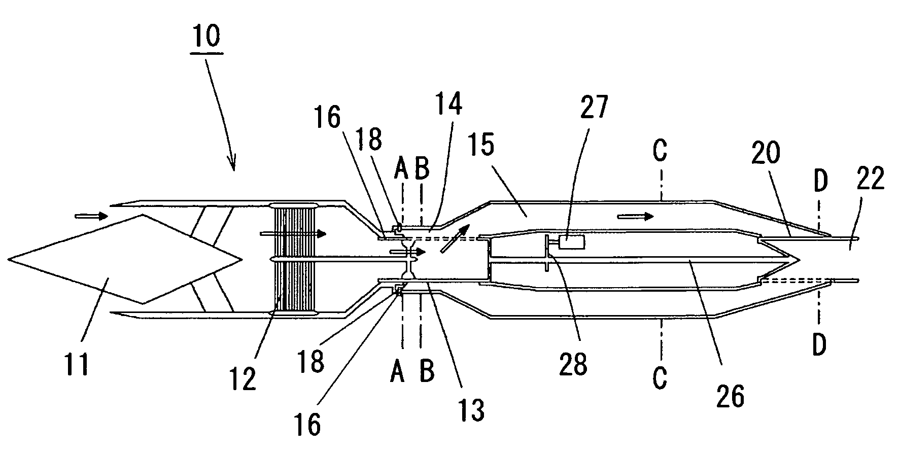
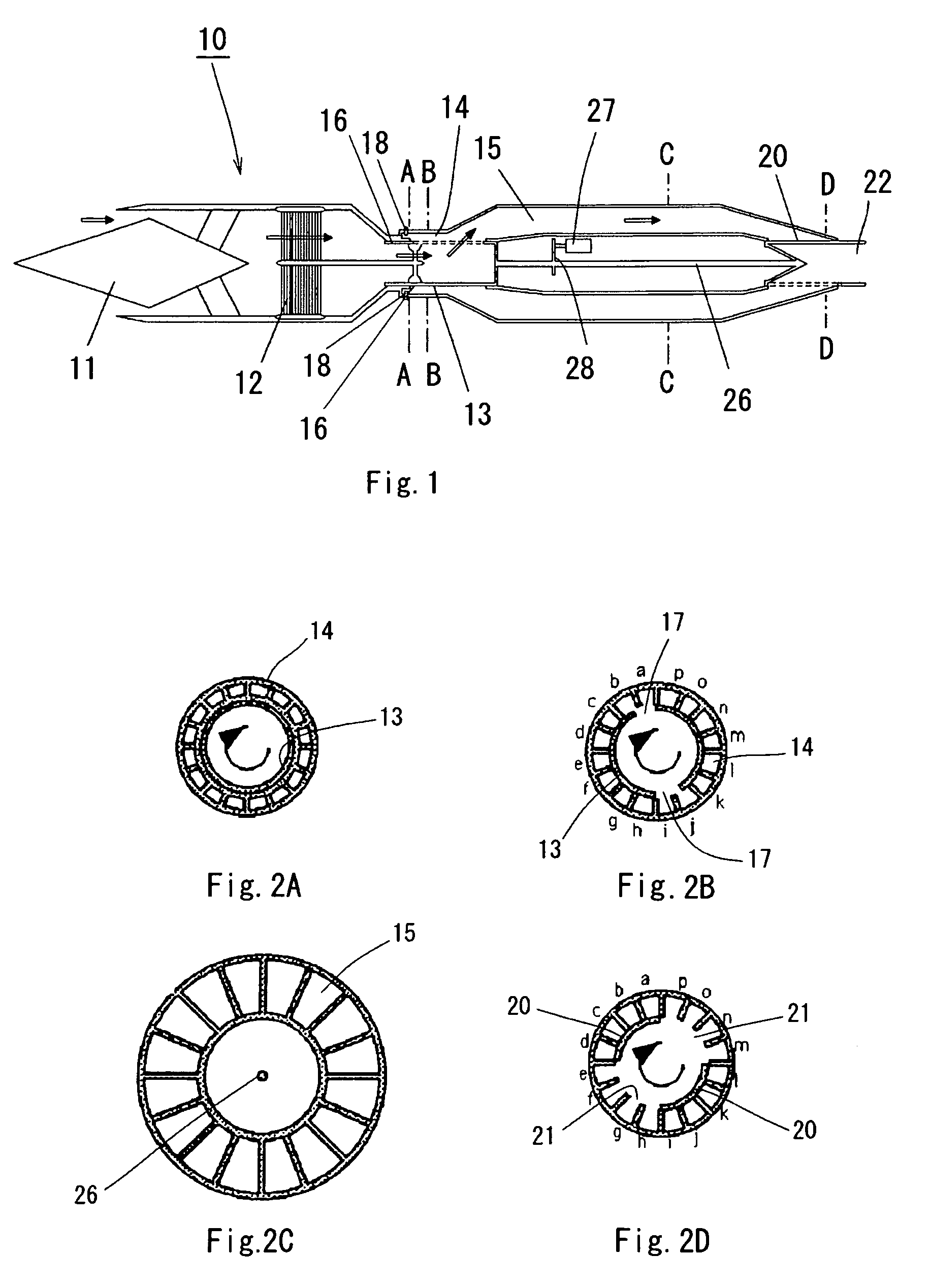
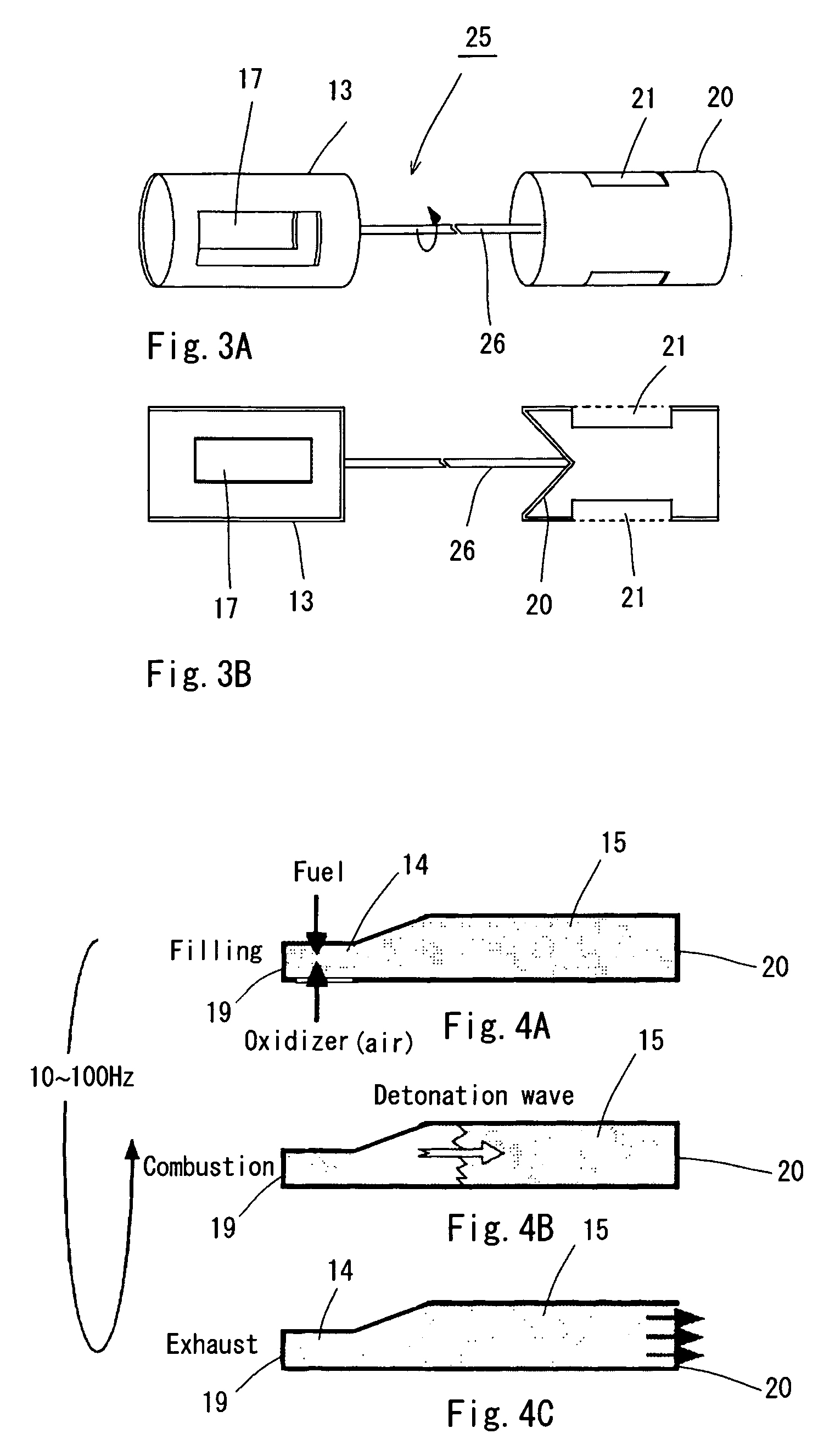
The present invention provides an engine that uses pulse detonation in the primary combustion process to increase thrust density in supersonic air-breathing engines at high altitude. The engine includes a supply valve and an exit valve that can open and close quickly, and a cylindrical rotary valve that can be rotated with precise timing. The valve is designed to increase pressure and density in the operating fluid without expansion during the filling process, and to withstand fatigue break from vibration and repetitive stress resulting from combustion. The engine also includes an intake to receive high-pressure air, which can be cooled to increase density, and a cylindrical rotary supply valve and exit valve that can be rotated together to open and close the outlet of the combustor. The valve is designed to improve rapid opening and closing performance and withstand fatigue break.

Problems solved by technology

For this reason, pulse detonation engines are considered unsuitable as supersonic air-breathing engines at high altitude, and the advantages of high specific impulse are not obtained.
Furthermore, since pulse detonation engines repeat combustion rapidly as described above, rapid opening and closing of the inlet valve supplying the gaseous mixture to the combustor is required, and they are subject to the problem of ready fatigue break due to vibration and repetitive stress resulting from combustion.

Method used


Image

  • Pulse detonation engine and valve
  • Pulse detonation engine and valve
  • Pulse detonation engine and valve

Examples


first embodiment

[0030]In order to verify the effect of providing an exit valve in the pulse detonation ramjet engine of the afore-mentioned embodiment, specific impulse and thrust density at Mach 1 through 3 was analyzed by simulation of the case of the combustor outlet closed with the exit valve when the gaseous mixture is supplied (compression ratio 100%), and the case of a similar combustor outlet in a conventional pulse detonation engine opened to atmosphere (compression ratio 0%). Results are shown in FIG. 6 and FIG. 7. Since airflow was the maximum at Mach 4 that can react into combustion in the combustor by the simulation, the inlet diameter was determined for Mach 4, and the inlet flow capture ratio reduced at below Mach 4. The results of the simulation showed that, when detonation occurred at an inlet maximum total pressure of 100% (in other words, with the combustor exit valve 20 closed and the combustor filled with gaseous mixture), an increase of approximately 700 seconds was apparent i...

second embodiment

[0031]Furthermore, in order to verify the cooling effect when a heat exchanger is provided in the outlet of the intake in the pulse detonation ramjet engine of the afore-mentioned embodiment, with the high-pressure air cooled by heat-exchange with liquid hydrogen being a coolant, change in thrust was analyzed by simulation of the cases of employing and not employing cooling in the first embodiment. Results are shown in FIG. 8. As shown in FIG. 8, a large increase in thrust at all Mach numbers was apparent when cooling was employed in comparison to the case of cooling not being employed. Furthermore, combustor inlet temperature at Mach 4 was reduced by approximately 200 K, and the flight envelope was able to be extended by approximately Mach 0.5 in comparison with the case of cooling not being employed.

[0032]According to the pulse detonation engine of the present invention, since pressure and density can be increased in the gaseous mixture supply process, and engine thrust density ma...


PUM


Abstract

Pressure and density of a gaseous mixture are increased in the process of introducing the gaseous mixture into the combustor of an air-breathing pulse detonation engine employing atmospheric oxygen as an oxidizer. The exit valve 20 able to be opened and closed is provided at the outlet of the combustor 15, an air cooler 12 is provided in the exit of the intake, and density is increased by exchange of heat of the air received at the intake with a coolant in the air cooler 12. Furthermore, by closing the exit valve 20 provided in the outlet of the combustor during the process of loading the gaseous mixture, transition to the detonation process is possible without expansion of the high-pressure high density air obtained by ram-compression at the intake.

Description

BACKGROUND OF THE INVENTION[0001]1. Field of the Invention[0002]The present invention relates to a pulse detonation engine for possible application as a propulsion engine for a spaceplane, high-speed aircraft, or launch rocket and the like, and more particularly to a pulse detonation ramjet engine suitable as an engine required for operation at flight speeds from takeoff to hypersonic, and a valve employed therein.[0003]2. Description of the Related Art[0004]The detonation phenomenon is a supersonic combustion phenomenon accompanied by a vertical shockwave at the front face of the combustion wave, and has a greater produced energy density than normal subsonic combustion (deflagnation), and generates a combustion gas of higher temperature and pressure. Research into the control and effective use of this [detonation phenomenon] has been conducted (see Popular Science Magazine, November 2003 “Detonation—The Battle for the Next Generation Engine”, and AIAA-95-2577 “A Rotary Valve Multip...

Claims


Application Information

Patent Timeline
Patent Type & Authority Patents(United States)
IPC IPC(8): F02K7/06F02K7/20F02C3/22F02C5/12F02C7/143F02C7/224F02K7/10F02K9/80F23C15/00F23R7/00
CPCF02K7/06F02K9/805F23C15/00F23R7/00F02C5/12
Inventor KOJIMA, TAKAYUKISATO, TETSUYAKOBAYASHI, HIROAKI
Owner JAPAN AEROSPACE EXPLORATION AGENCY
Learn More