
Thermodilution catheter having a safe, flexible heating element

a flexible heating element and safe technology, applied in the field of thermodilution catheters, can solve the problems of enormous cross-talk and error, and achieve the effects of reducing the overall cross-sectional area of the catheter, preventing localized overheating, and being safe to use in clinical settings

Inactive Publication Date: 2007-08-14
EDWARDS LIFESCIENCES CORP
View PDF81 Cites 23 Cited by
  • Summary
  • Abstract
  • Description
  • Claims
  • Application Information

AI Technical Summary

Benefits of technology

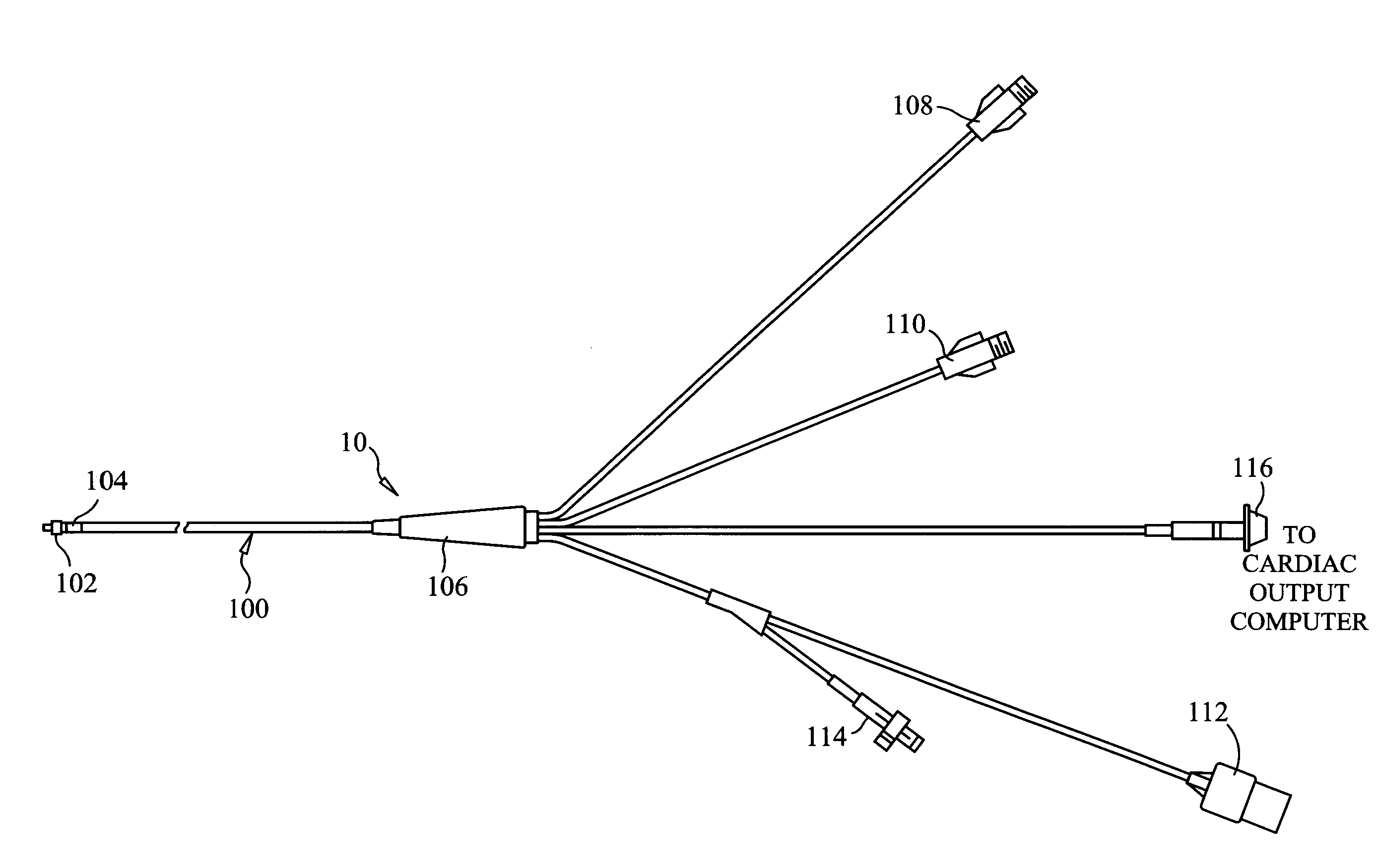
[0019]A safe, accurate thermodilution measurement may be made in accordance with the present invention by using a catheter having a heating filament which resides internal to the catheter body, either in a preformed catheter lumen or beneath an outer sheath, and which preferably does not directly contact the blood. The heating filament is preferably made of a thin, flexible material which may be wrapped either on the exterior of the catheter body wall and then covered by an external sheath material so that the heating filament material is not exposed to the blood or on the outer surface of a supporting sheath inserted into the catheter lumen. The heating filament so designed supplies a quantity of heat to the flowing blood which is used for measuring the volumetric blood flow using an indicator dilution equation. During use, the filament temperature is preferably measured simultaneous with the thermodilution measurement without the use of a second measuring transducer—not to calculate velocity, but so that a safe filament temperature may be maintained. This is accomplished in a preferred embodiment by forming the heating filament of a material which has a resistance proportional or inversely proportional to its temperature.
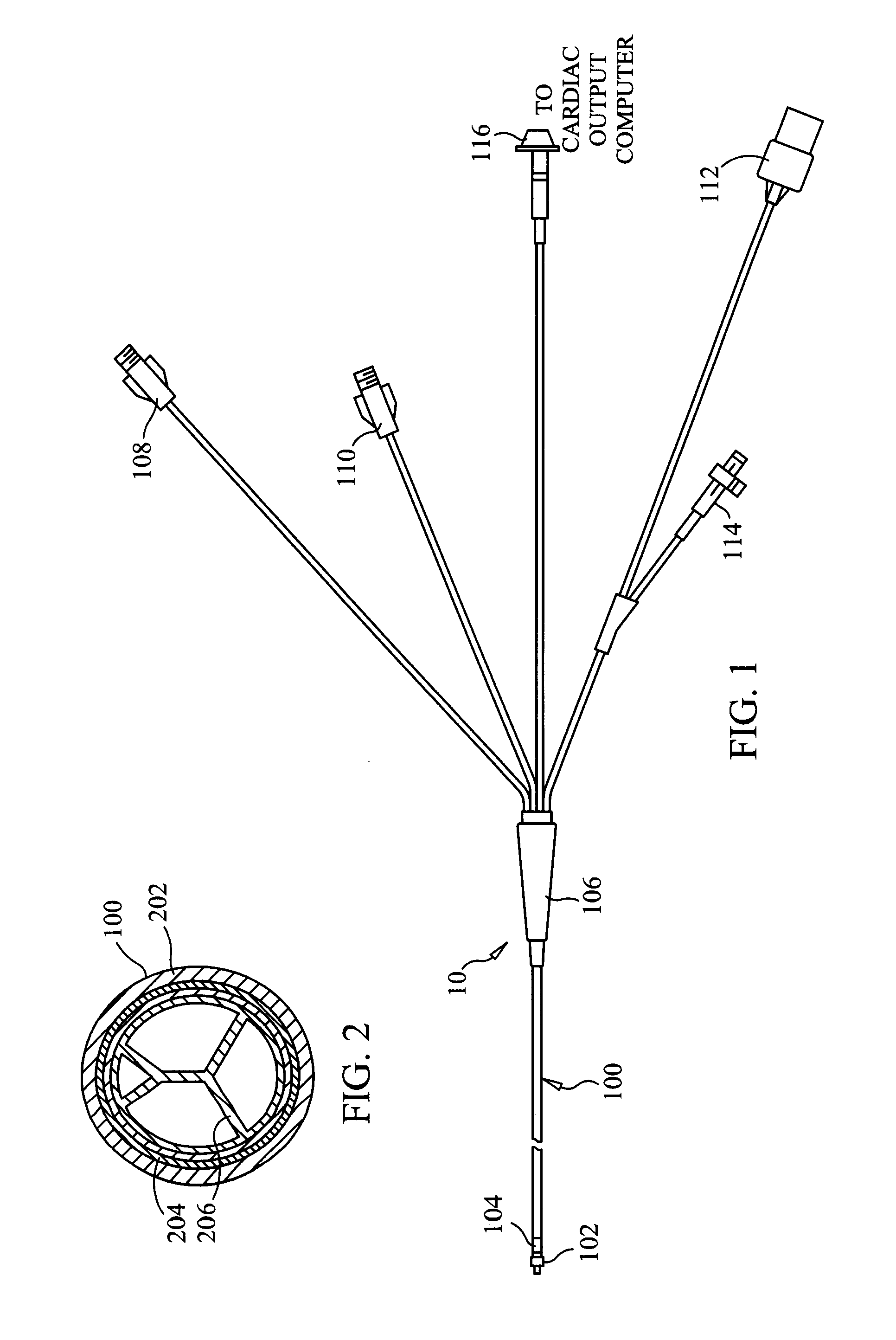
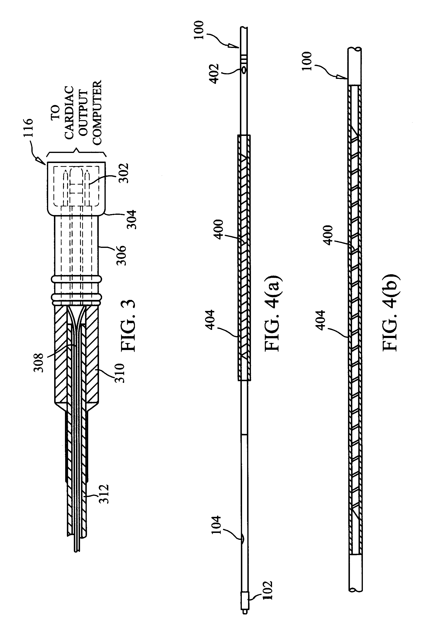
[0025]In accordance with a preferred embodiment of the invention, the catheter member comprises a substantially cylindrical body wall portion and an outer sheath, where the heating filament is wrapped in a thin layer about the body wall portion of the catheter member and enclosed by the sheath. The sheath may be a flexible material formed by extrusion or blow molding or a flexible material which shrinks to form-fit the heating filament and the body wall portion when a sufficient quantity of heat is applied thereto. A layer of material with high thermal conductivity may also be disposed about the heating filament so as to create a more uniform surface temperature. The body wall portion may also have a reduced diameter in the region where the heating filament is wrapped therearound such that the resulting total diameter in that region is approximately equal to the diameter of the body wall portion in other regions. In some embodiments, the sheath material may actually contain the resistive heating material so as to form one element, thereby eliminating the need for a separate filament and sheath.
[0036]reducing power to the heating filament when resistance (and consequently the temperature) of the heating filament exceeds a predetermined resistance amount (temperature). These steps prevent localized overheating and thus help assure patient safety.
[0052]Thus, by providing a heating filament which is minimally thin, heat from the filament may be transferred to the surrounding blood in accordance with the invention without significantly increasing the overall cross-sectional area of the catheter. Also, by providing a surface coating for the resulting catheter which has no rough areas to induce blood clot formation, the thermodilution catheter of the invention may be more safely used in clinical settings. Moreover, by monitoring the heating filament temperature, localized overheating may be prevented. Other elements or drugs, such as heparin, antibiotics and the like may be added to the filament sheath to reduce the possibility of any complications as a result of the measurements using the catheter of the invention.

Problems solved by technology

The classical thermodilution catheter cannot be used in such a case since it is necessary to have the indicator flow under and past the detection thermistor or thermocouple, which in the case of “retro grade” blood flow induces an enormous amount of cross-talk and error.

Method used


Image

  • Thermodilution catheter having a safe, flexible heating element
  • Thermodilution catheter having a safe, flexible heating element
  • Thermodilution catheter having a safe, flexible heating element

Examples


Embodiment Construction

[0065]A system with the above-mentioned beneficial features in accordance with presently preferred exemplary embodiments of the invention will be described below in detail with reference to FIGS. 1–8. It will be appreciated by those of ordinary skill in the art that the description given herein with respect to those figures is for exemplary purposes only and is not intended in any way to limit the scope of the invention. All questions regarding the scope of the invention may be resolved by referring to the appended claims.

[0066]A detailed description of intra vascular catheters is not given herein, for the features of different types of catheters, namely flow-directed pulmonary artery catheters, left ventricular angiography catheters, and the like are well known to those familiar to the art. Some unique features of such catheters are described by way of example in U.S. Pat. Nos. 3,746,003; 3,634,924; 3,995,623; 4,696,304; 4,718,423; and 4,721,115.

[0067]FIG. 1 illustrates a proximal ...


PUM


Abstract

A thermodilution catheter having a heating filament which is fabricated so as to be thin and flexible enough to avoid contact with the patient's blood. The heating filament is either inserted in a preformed catheter lumen, incorporated into a wall of the catheter body itself, or wrapped around the catheter body wall and surrounded by an external sheath. Generally, the covering of the heating filament is minimally thin so as to allow the heat from the heating filament to be transferred to the surrounding blood and to minimally increase the overall cross-sectional area. Since the heating filament does not directly touch the patient's blood, the outer surface may be made smooth so as to prevent inducement of blood clots. In addition, the heating filament may be maintained at a safe temperature by forming the heating element of a flexible material having a high temperature coefficient of resistance, low thermal capacitance and high thermal conductivity. Preferably, the temperature coefficient of resistance of the material forming the heater filament is greater than 0.001 Ω / Ω-° C. and the resistance of the heating filament is proportional or inversely proportional to its temperature. By monitoring this resistance, the application of power to the heating filament may be regulated to prevent overheating of the heating filament. Calibration techniques are also disclosed whereby a memory containing encoded calibration information is disposed within or connected to a connector of the catheter. This memory may also include a program segment used by a cardiac output computer having a cardiac output calculation program, whereby the portion of code stored in the memory must be input into the cardiac output computer before the determination of the cardiac output can be performed. As a result of these improvements, the invention enables the thermodilution cardiac output calculation to be performed quite safely and accurately in a clinical setting.

Description

[0001]This is a Division of application Ser. No. 08 / 049,231 filed on Apr. 19, 1993, Now U.S. Pat. No. 6,387,052 which is a continuation of application Ser. No. 07 / 647,578 filed on Jan. 29, 1991, now abandonedBACKGROUND OF THE INVENTION[0002]1. Field of the Invention[0003]The present invention relates to a thermodilution catheter, and more particularly, to a thermodilution catheter having a flexible heating filament disposed therein for applying heat to the patient's blood for purposes of measuring cardiac output, volumetric blood flow, blood pressure, blood volume, blood components and the like.[0004]2. Description of the Prior Art[0005]As is well known, catheters have been developed for purposes of applying physiologic preparations directly into the blood streams of animals or humans or for measuring cardiovascular parameters such as cardiac output, blood pressure, blood volume, blood components and the like. Conventional catheters are made from various materials including plastics...

Claims


Application Information

Patent Timeline
IPC IPC(8): A61B5/02A61B5/00A61B5/028A61B18/14
CPCA61B5/028A61B5/1495A61B5/6855A61B5/6856A61B5/6857A61B18/14A61B2017/00482A61B2018/00178A61B2018/00666A61B2018/00678A61B2018/00708A61B2018/00791A61B2018/00797A61B2018/00815A61B2018/00821A61B2018/00988A61B2562/08
Inventor QUINN, MICHAEL D.YELDERMAN, MARK L.
Owner EDWARDS LIFESCIENCES CORP
Learn More