Wireless communication system with high efficiency/high power optical source

Inactive Publication Date: 2007-08-14
RAYTHEON CO
View PDF15 Cites 68 Cited by
  • Summary
  • Abstract
  • Description
  • Claims
  • Application Information

AI Technical Summary

Benefits of technology

[0009]The present invention provides an optical communication system with an optical signal transmitter at the last mile for transmitting information at increased frequency bandwidths. The optical signal transmitter includes a high efficiency/high power optical source which operates at high efficiency, high power optical frequencies such as the infrared and visible light bands, and which may extend beyond in

Problems solved by technology

Little or no feasible technology presently exists, however, to deliver high frequency bandwidth, and in particular two-way bandwidth, at the user terminal end of existing communication networks.
Because the legacy copper lines were designed for performance that did not contemplate today's fiber optic capabilities, the end users with copper lines cannot avail themselves of the high bit rates that a modern long haul infrastructure can provide.
Quite simply, the legacy links as well as the architecture of the central office (telephone exchange) cannot deliver the information transfer capability desired for all the data, video, etc.
The end user has thus been limited by his or her local drop (or “last-mile”) connection to the service provider.
Fiber optic cable lines and satellit

Method used


Image

  • Wireless communication system with high efficiency/high power optical source
  • Wireless communication system with high efficiency/high power optical source
  • Wireless communication system with high efficiency/high power optical source

Examples


Embodiment Construction

[0030]The present invention will now be described with reference to the drawings, in which like reference numerals are used to refer to like elements throughout.

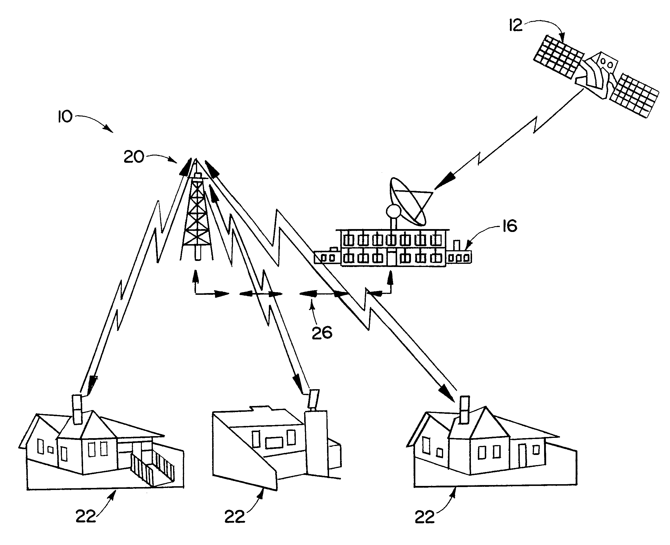
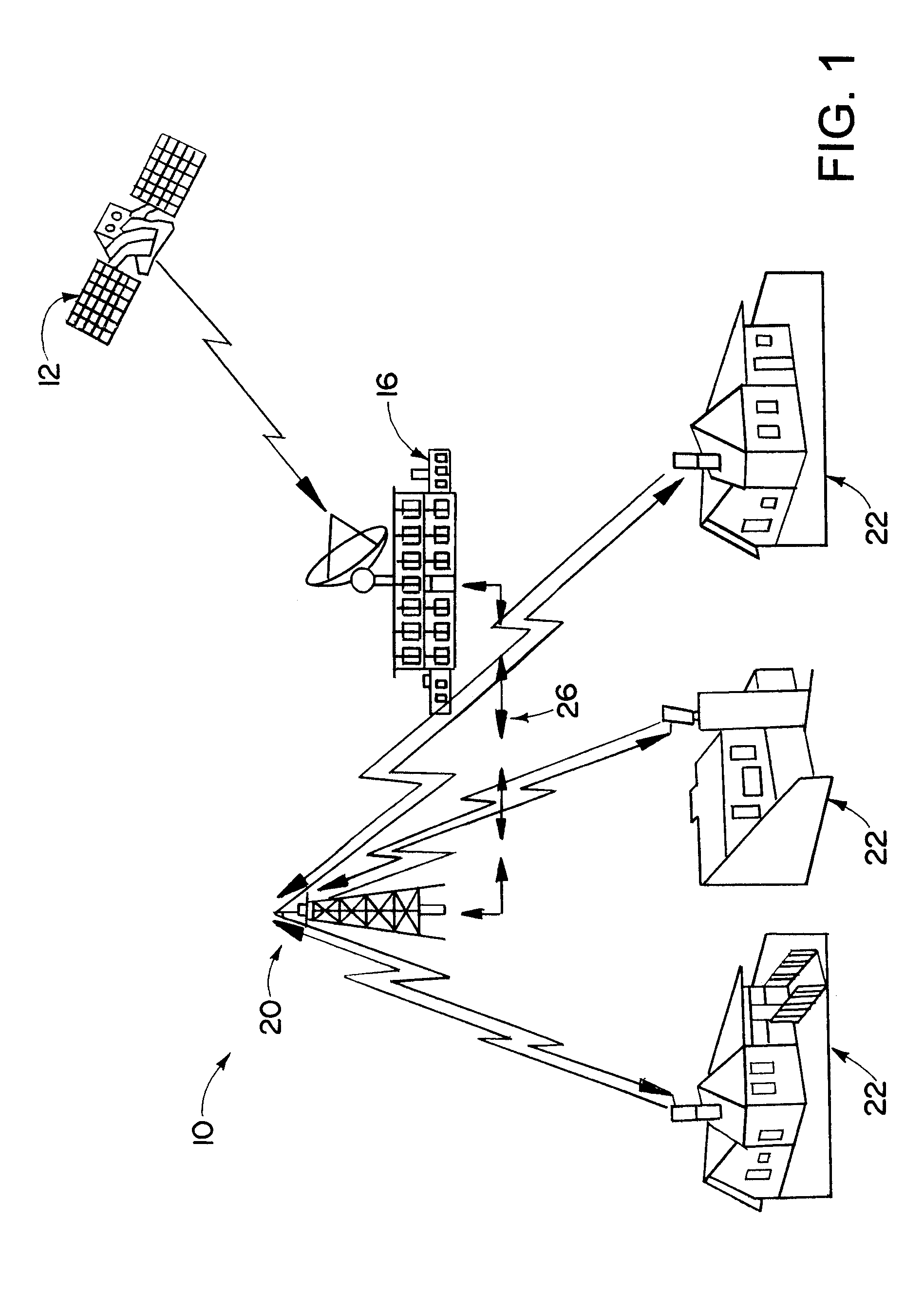
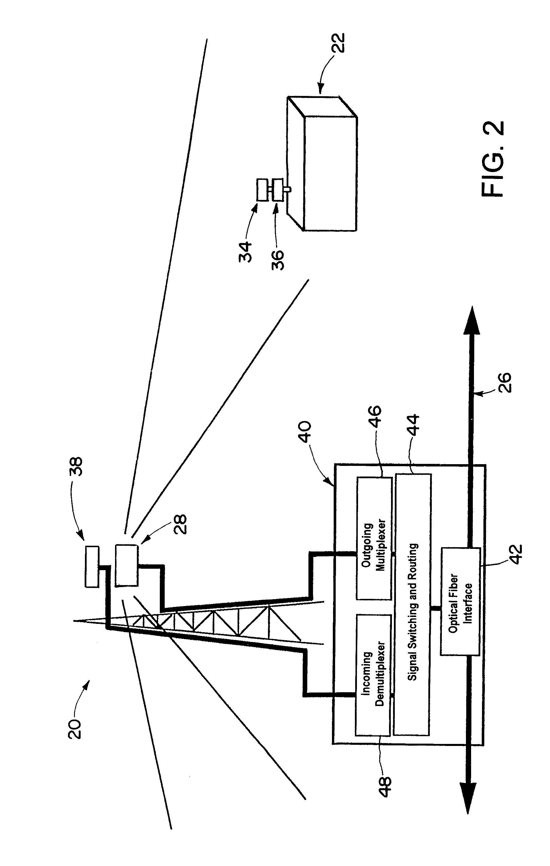
[0031]Referring now in detail to the drawings and initially to FIGS. 1 and 2, there is illustrated an optical communication system 10 in accordance with the present invention. The optical communication system 10 includes a broadband data source 12 such as a satellite, an intercity optical fiber trunk line, or the like. The data source 12 provides broadband data such as multichannel video programming, on-demand programming, broadband telecommunications, etc. The optical communication system 10 further includes a service provider 16 such as a cable service provider. The service provider 16 receives data from the data source 12 and provides such data to a network of optical signal communication stations 20, only one of which is shown in FIG. 1. The optical communication stations 20 serve to communicate information from the serv...


PUM


Abstract

An optical communication system is provided which includes an optical signal transmitter which communicates high bandwidth, high power frequencies. The optical signal transmitter includes a high efficiency/high power optical source such as an optical magnetron or a phased array source of electromagnetic radiation, and a modulator element. The modulator element may be within a resonance cavity of the high efficiency/high power optical source (intra cavity) or external to the cavity (extra cavity). The modulator element serves to modulate output radiation of the high efficiency/high power optical source to produce a modulated high frequency optical signal which may be transmitted through the air. The optical signal transmitter is particularly useful in providing the last mile connection between cable service operators and end users.

Description

RELATED APPLICATION DATA[0001]This application is a continuation-in-part of U.S. patent application Ser. No. 09 / 798,623, filed Mar. 1, 2001 now U.S. Pat. No. 6,504,303, which is a continuation-in-part of U.S. patent application Ser. No. 09 / 584,887, now U.S. Pat. No. 6,373,194, filed Jun. 1, 2000, U.S. patent application Ser. No. 10 / 050,744, filed Jan. 16, 2002, which is a divisional of U.S. patent application Ser. No. 09 / 584,887, and U.S. patent application Ser. No. 09 / 995,361, filed Nov. 27, 2001, all of which are hereby incorporated herein by reference in their entirety.TECHNICAL FIELD[0002]The present invention relates generally to wireless communication systems for communicating information, for example, video and voice data, and more particularly to a wireless optical communication system with a high efficiency / high power optical source.BACKGROUND OF THE INVENTION[0003]The need for network architectures that provide broad frequency bandwidth is evident from the increased user d...

Claims


Application Information

Patent Timeline
IPC IPC(8): H04B10/00H01J23/20H01J23/16H01J23/213H01J23/22H01J25/50H04B10/10
CPCH01J23/165H01J23/213H01J25/50H04B10/1125H01J23/22Y02B60/50
Inventor SMALL, JAMES G.
Owner RAYTHEON CO
Why Eureka
Try Eureka