Method for manufacturing a diffuser for a backlight module

a backlight module and manufacturing method technology, applied in the direction of photomechanical equipment, instruments, originals for photomechanical treatment, etc., can solve the problems of complex sieving of the particle size of the scattering particles, the non-uniform surface of the sandblast method, and the inability to uniformly disperse the scattering particles in the adhesive, etc., to achieve excellent diffusing efficiency, avoid the complex step of dispersing particles, and simplify the manufacturing of the diffuser

Inactive Publication Date: 2007-08-21
CPT TECH GRP
View PDF4 Cites 5 Cited by
  • Summary
  • Abstract
  • Description
  • Claims
  • Application Information

AI Technical Summary

Benefits of technology

[0009]The object of the present invention is to provide a method for manufacturing a diffuser for a backlight module, wherein the masking particles are utilized for carrying out the photolithography processes, which simplifies the manufacturing of a diffuser, avoids the complex step of dispersing particles, and provides a diffuser having an excellent diffusing efficiency.

Problems solved by technology

The sandblast method firstly forms a non-uniform surface on the transparent substrate by sand grinding.
The disadvantages of the particle adhesion method lie in that the scattering particles cannot be dispersed uniformly in the adhesive due to the gravity or static electricity factors, and the sieving of particle size of the scattering particles is complex and needs to be done carefully because it will affect the performance of light diffusion.
Besides, those scattering particles are mostly made of hard inorganic materials, such as silica or calcium carbonate, which will damage the surface of a liquid crystal (LC) cell through direct contact and therefore a passivation layer is further needed.
However, the sandblast method cannot precisely control the roughness of the surface and the uniformity thereof so that the quality of light guide is not easily controlled in mass production.

Method used


Image

  • Method for manufacturing a diffuser for a backlight module
  • Method for manufacturing a diffuser for a backlight module
  • Method for manufacturing a diffuser for a backlight module

Examples


Embodiment Construction

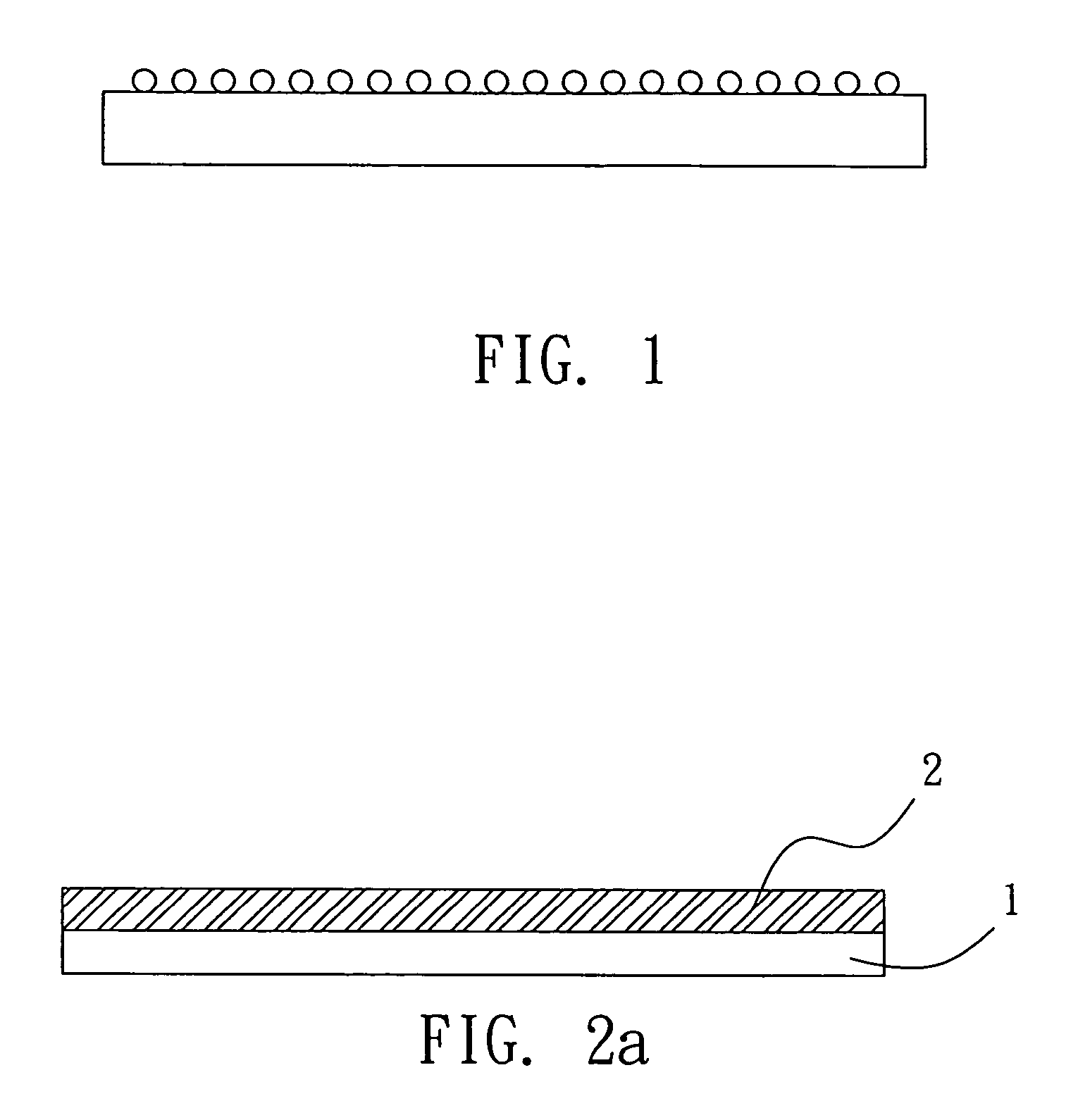
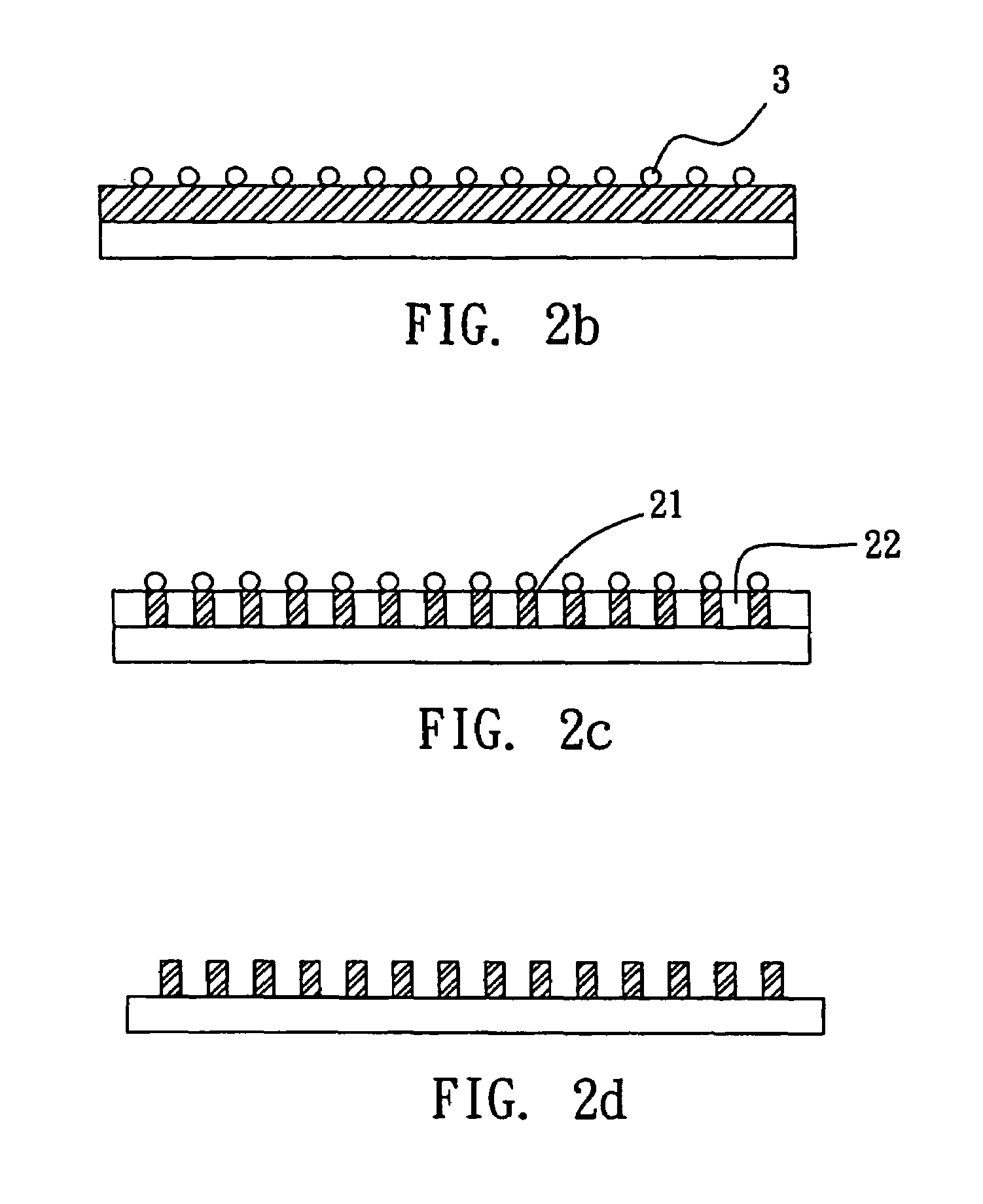
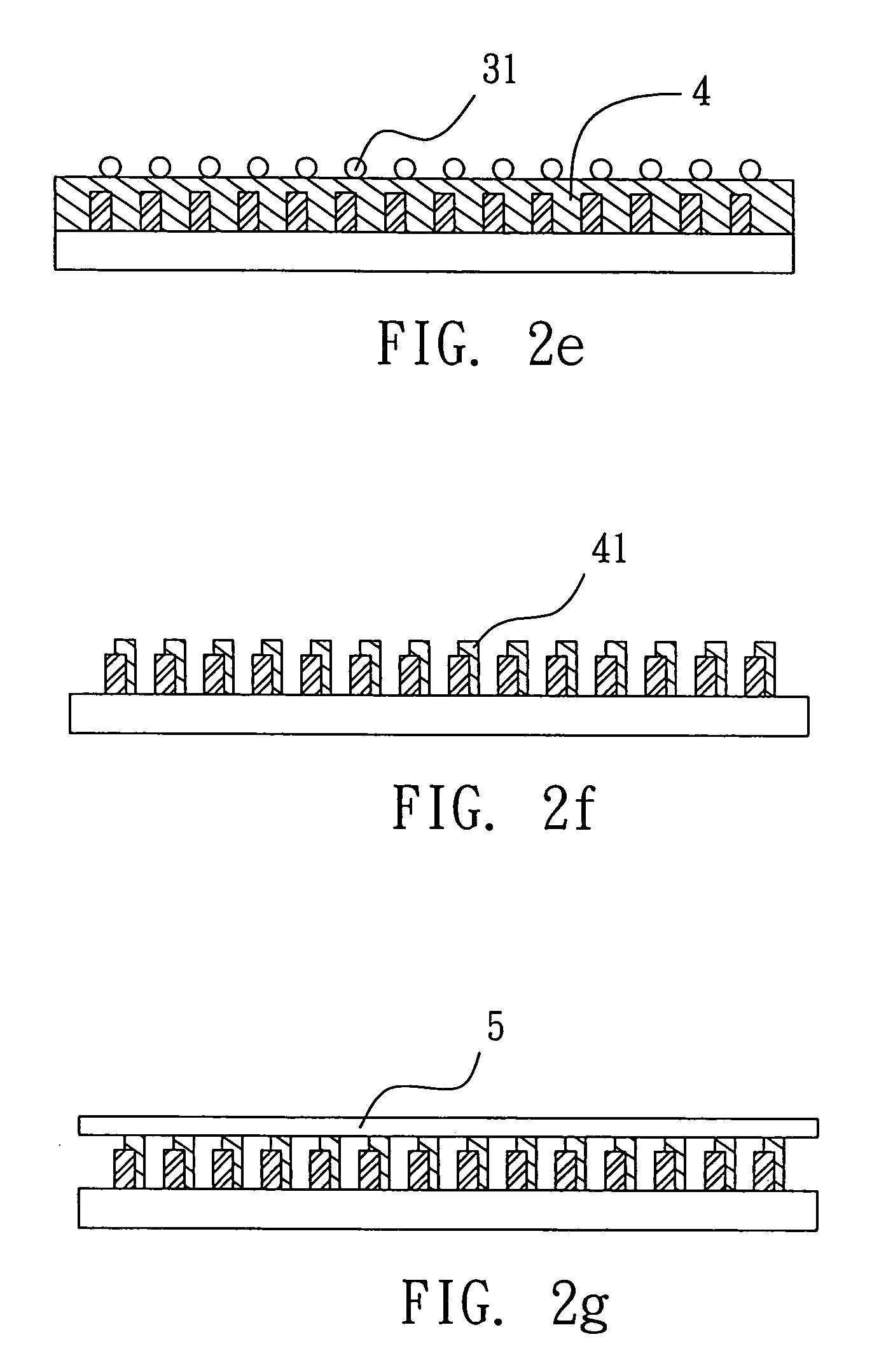
[0015]The material of the transparent substrate is not restricted in the method for manufacturing a diffuser for a backlight module of the present invention. Preferably, the transparent substrate is made of acrylates, polyethylene terephthalate (PET), or polycarbonate (PC). The kind of the photoresist is not restricted. Preferably, the photoresist has at least one photo-sensitive polymer and one photo initiator. More preferably, the photoresist is a polyacrylate-based photoresist. The material of the masking particles in the present invention is not restricted, and preferably is selected from the group consisting of glass, TiO2, silica, and polystyrene. The particle sizes of the masking particles are not restricted, and may be adjusted according to the light source. Preferably, the particle sizes range from 100 nm to 50 μm. The material of the passivation layer in the method of the present invention is not restricted. Preferably, the passivation layer is made of polyacrylates, polyc...


PUM

PropertyMeasurementUnit
particle sizeaaaaaaaaaa
particle sizesaaaaaaaaaa
particle sizeaaaaaaaaaa

Abstract

A method for manufacturing a diffuser for a backlight module is disclosed. The method includes providing a transparent substrate; forming a first transparent photoresist layer on the transparent substrate; spreading a plurality of masking particles on the first transparent photoresist layer; exposing and developing the first transparent photoresist layer; removing the masking particles; etching the exposed region of the first transparent photoresist layer to form a first scattering array; and optionally forming a passivation layer on the first transparent photoresist layer.

Description

BACKGROUND OF THE INVENTION[0001]1. Field of the Invention[0002]The present invention relates to a method for manufacturing a diffuser for a backlight module and, more particularly, to a method for manufacturing a diffuser using particles as a mask.[0003]2. Description of Related Art[0004]Currently, flat panel displays, such as LCDs and PDPs are gradually replacing the traditional CRT displays and becoming the main stream of displays due to their light weight and thin size.[0005]Contemporary flat panel displays use backlight modules as their sources of light. Generally, a backlight module includes a light source, a light guide, and two diffusers. The diffusers are used to make a uniform dispersion of light and prevent the displaying zone of a display from suffering non-uniform illumination.[0006]The common methods for manufacturing a diffuser include the particle adhesion method and the sandblast method. In the particle adhesion method, the scattering particles are adhered on the su...

Claims


Application Information

Patent Timeline
Patent Type & Authority Patents(United States)
IPC IPC(8): G03C5/00G02B5/02G03F1/00G03F7/16
CPCG02B5/0215G02B5/0221G03F7/168G02B5/0278G03F1/14G02B5/0268G03F7/0035G03F7/2016
Inventor CHAO, CHING-YUHSIEH, WEN-JIUNN
Owner CPT TECH GRP
Why Eureka
Try Eureka