Method for encapsulation of light emitting polymer devices

a technology of light-emitting polymer and encapsulation, which is applied in the direction of discharge tube luminescnet screen discharge tube/lamp details, etc., can solve the problems of low air permittivity, ridged finished display, dark spots, shorting and other failures of the device, etc., and achieve low air permittivity

Active Publication Date: 2007-08-28
SUMITOMO CHEM CO LTD
View PDF10 Cites 7 Cited by
  • Summary
  • Abstract
  • Description
  • Claims
  • Application Information

AI Technical Summary

Benefits of technology

[0010]This invention provides a cost-effect manufacturing process for encapsulating an LEP device with an air-stable electrode (cathode) between two flexible sheet materials, where the first sheet may act as the substrate and the second sheet as a cover and at least one of the sheets is transparent. Both encapsulating sheets and, as required, an adhesive system binding the sheets together, should provide sufficient environmental barriers with low moisture vapor transmission rates (MVTR) and oxygen transmission rates (OTR) for LEP device long life operation. The encapsulating sheets may be selected from commercially available materials in sheet or roll form. The transparent encapsulating sheet may be comprised of the materials as described in the above referenced U.S. Pat. Nos. 6,268,695, 6,146,225 and 5,734,225. The second sheet need not be transparent, and may be comprised of polymer and metalization layers. The encapsulating sheets can, for example, be laminated together, sandwiching the LEP device in a vacuum, or oxygen free, inert gas environment.
[0011]Prior to the laminating step the LEP device may be heated and placed in a vacuum to remove moisture, air and solvents. The process may also be designed for roll to roll, sometimes called web based processing, where the LEP device and / or encapsulating sheet material are in a continuous roll format with an adhesive with low air permittivity, such as some UV or thermal curable epoxies, or a melt lamination process used to attach the encapsulating sheets. For LEP device with short lifetime requirements, the encapsulating material may be in liquid form and applied by spraying, dipping, doctor balding, and the like, or printing, such as screen printing, roller coating or lithographic application in single or multiple layers. Such material may also contain desiccants to further remove water and / or oxygen.

Problems solved by technology

Including these typical device design, all LEP devices are currently limited in their use due to poor environmental stability.
The ingress of water and oxygen into the device creates catastrophic failure mechanisms (e.g., photo-oxidation, electrochemical reactions, metal migration, delamination of the device, etc.) resulting in dark spots, shorting and other failures of the device.
These problems, and others, are compounded for LEP devices made on thin flexible plastic substrates because these substrates typically provide little protection against oxygen and moisture ingress.
The problem with this technique is that the finished display is ridged, heavy, bulky, fragile and expensive.
The low work function metal cathodes, typically Calcium or Lithium, are not air-stable and quickly oxidize in the presence oxygen.
This makes manufacturing difficult, time consuming and expensive.
However, even with an air-stable electrode, moisture and air need to be removed from the device and the device needs to be encapsulated prior to operation because of irreversible electrochemical reactions that can occur in the device in the presence of moisture, air and electric fields.

Method used


Image

  • Method for encapsulation of light emitting polymer devices
  • Method for encapsulation of light emitting polymer devices
  • Method for encapsulation of light emitting polymer devices

Examples


Embodiment Construction

[0016]The present invention will now be described in detail with reference to the drawings, which are provided as illustrative examples of the invention so as to enable those skilled in the art to practice the invention. Notably, the figures and examples below are not meant to limit the scope of the present invention. Where certain elements of the present invention can be partially or fully implemented using known components, only those portions of such known components that are necessary for an understanding of the present invention will be described, and detailed descriptions of other portions of such known components will be omitted so as not to obscure the invention. Further, the present invention encompasses present and future known equivalents to the known components referred to herein by way of illustration.

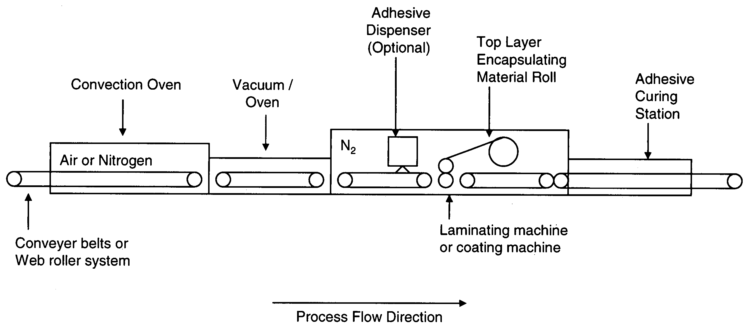
[0017]The LEP device having an air-stable electrode (cathode) according to an embodiment of the present invention may be fabricated in an ambient air (i.e., atmospheric) e...


PUM

PropertyMeasurementUnit
pressureaaaaaaaaaa
pressureaaaaaaaaaa
timeaaaaaaaaaa

Abstract

A cost effective manufacturing process encapsulates a light emitting polymer (LEP) device between two flexible sheet materials, where one sheet may act as the substrate for the LEP device and the other sheet may act as a cover for the LEP device, and at least one of the sheets is transparent. Both encapsulating sheets and, as required, an adhesive system binding the sheets together provide sufficient environmental barriers with low moisture vapor transmission rates (MVTR) and oxygen transmission rates (OTR). The encapsulating sheets may, for example, be laminated together, sandwiching the LEP device in a vacuum, or oxygen / moisture free, and inert gas environment. Prior to encapsulation the LEP device may be heated and placed in a vacuum to remove moisture, air and residual solvents. The process may also be designed for roll to roll, sometimes called web based processing, where the LEP device and / or encapsulating sheet material are in a continuous roll format with an adhesive with low air permittivity, such as some UV or thermal curable epoxies, or a melt lamination process used to attach the encapsulating sheets. For LEP devices with short lifetime requirements, the encapsulating material may be in liquid form and applied by spraying, dipping, doctor balding, and the like, or printing, such as screen printing, roller coating or lithographic application in single or multiple layers. Such material may also contain desiccants to further remove water and / or oxygen.

Description

CROSS-REFERENCE TO RELATED APPLICATIONS[0001]This application claims the benefit of priority under 35 U.S.C. § 119(e) from U.S. Provisional Application No. 60 / 436,691 to Wilkinson et al., filed Dec. 27, 2002 and entitled “Process for Encapsulation of Light Emitting Polymer Devices,” which is incorporated herein by reference in its entirety and for all purposes.BACKGROUND OF THE INVENTION[0002]1. Field of the Invention[0003]This invention relates to electroluminescent devices, and more particularly to the fabrication of light emitting polymer devices. Specifically, this invention describes a unique, low cost, encapsulation process that provides a barrier for preventing ambient moisture and oxygen in light emitting polymer devices with air-stable electrodes (cathodes).[0004]2. Description of the Related Art[0005]Typical light emitting polymer (LEP) devices have been under development for flat panel and other display applications for many years. There are other patents that teach how d...

Claims


Application Information

Patent Timeline
Patent Type & Authority Patents(United States)
IPC IPC(8): B29C65/00B29C35/08B29C70/70B29C70/88H01L51/52H01L51/56
CPCH01L51/5237H01L51/56Y10T156/109Y10T156/103H10K50/841H10K50/844H10K71/40H10K71/00
Inventor WILKINSON, MATTHEW C.CARTER, SUSAN A.KREGER, MELISSA
Owner SUMITOMO CHEM CO LTD
Why Eureka
Try Eureka