In particular, network transformers have the disadvantages that they are heavy and they incur relatively
high energy losses.
One solution is to use superconducting transformers although, inter alia, they are more problematic for vehicle use owing to the cooling systems that are required, than for stationary systems, and are therefore not yet technically proven at the moment.
Until now, the disadvantages here have been the high technical complexity and a range of restrictions which prevent universal use, as will be explained in the following text.
While avoiding the need for a network
transformer by being connected directly to the overhead wire
voltage, these high voltages require semiconductors or converter elements to be connected in series in the
power electronics—as well as a high degree of technical complexity overall.
On the other hand, the disadvantages include:The increased motor isolation that is required has a disadvantageous effect on the physical motor size, on the motor weight and / or on the
motor efficiency.The power matching that is absolutely essential between the series-connected converter elements (when the motors are subject to different loads) requires the use of complex motor windings with a large number of connections carrying high voltages (so-called 3-star motors).The number of traction motors cannot be varied freely.
In order to limit the disadvantageous effects of the items mentioned above, as large a number of high-power motors as possible should be chosen.The high
DC voltage components between the series-connected converter elements make it harder to provide reliable isolation in actual conditions (
dirt,
moisture).The feed for the auxiliary systems requires considerable additional complexity.In order to maintain a restricted operating capability in the event of failures in the power section or in the event of insulation faults in the motors, additional switching devices are required (redundancy).b) Use of conventional traction motors (with a
low load on the insulation) without DC isolation from the overhead wire close to ground potential, for example as known from DE 197 21 450 C1.
This fundamental
disadvantage, in particular the size of the energy stores that are required, prevents universal use of corresponding variants.c) DC isolation of the motors from the overhead wire using a number of individual medium-frequency transformers, which each have associated individual, series-connected converter elements, for example as known from Schibli / Rufer, Single and Three-Phase Multilevel
Converters for Traction Systems 50 Hz / 16 ⅔ Hz, LEI, Lausanne, pages 4.210-4.215.
On the other hand, the disadvantages are as follows:The large number of power-electronic converter stages which are located in the energy flowpath between the overhead wire and the traction motors (high degree of complexity, relatively
high energy losses).The high degree of complexity for energy stores (2
DC voltage capacitors plus any series resonant circuits) for
smoothing the power pulsation at twice the network frequency.The large number of individual medium-frequency transformers required, which in total are worse than one central
transformer in terms of the weight and the space required.
Splitting into a large number of individual transformers is also disadvantageous, and occupies a large amount of space, as a result of the (in total) numerous transformer connection points on the high-
voltage side.As in the first-mentioned variant, the high
DC voltage components between the series-connected converter elements make it harder to provide reliable isolation in actual conditions (
dirt,
moisture).The feed for auxiliary systems requires considerable additional complexity.In order to maintain a restricted operating capability in the event of failures in the power section or insulation faults in the motors, additional switching devices are required (redundancy).d) DC isolation of the motors from the overhead wire using a medium-frequency transformer which is fed from the overhead wire by means of a direct converter, for example as known from DE 26 14 445 C2 or Östlund, Influence of the
control Principle on a High-
Voltage Inverter System for Reduction of Traction-
Transformer Weight, EPE, Aachen 1989.
However, for several reasons, the provision of a direct converter with thyristors does not satisfy present or future requirements.
The major disadvantages are:The achievable
medium frequency is restricted to a few 100
Hertz owing to the commutation times in a circuit fitted with thyristors.
This frequency is not sufficient to significantly reduce the weight of the medium-frequency transformer.The stringent interference current limit values (minimizing
harmonic currents in the railroad network) for modern locomotives cannot be complied with because, in principle, the spectrum includes twice the
medium frequency and other interference frequencies.
This makes it harder to provide isolation (winding isolation, air gaps, creepage paths) for the transformer.
However, the following disadvantages of direct
converters are also associated with these embodiments.
This has a disadvantageous influence on the physical size and efficiency of the medium-frequency transformer.The
filter capacitor which is required on the network side and can cause interference resonances in the railroad network, and which can lead to the circuit having undesirably
low input impedances for higher-frequency interference currents.In contrast to converters with a DC
voltage intermediate circuit (“U converters”), the power semiconductors have no protection against high-energy network overvoltages, as provided by a
capacitor on the DC voltage side.
No suitable circuits or methods are known for producing staircase voltages with a low
harmonic content (analogously to multipoint U converters) for
matrix converters.
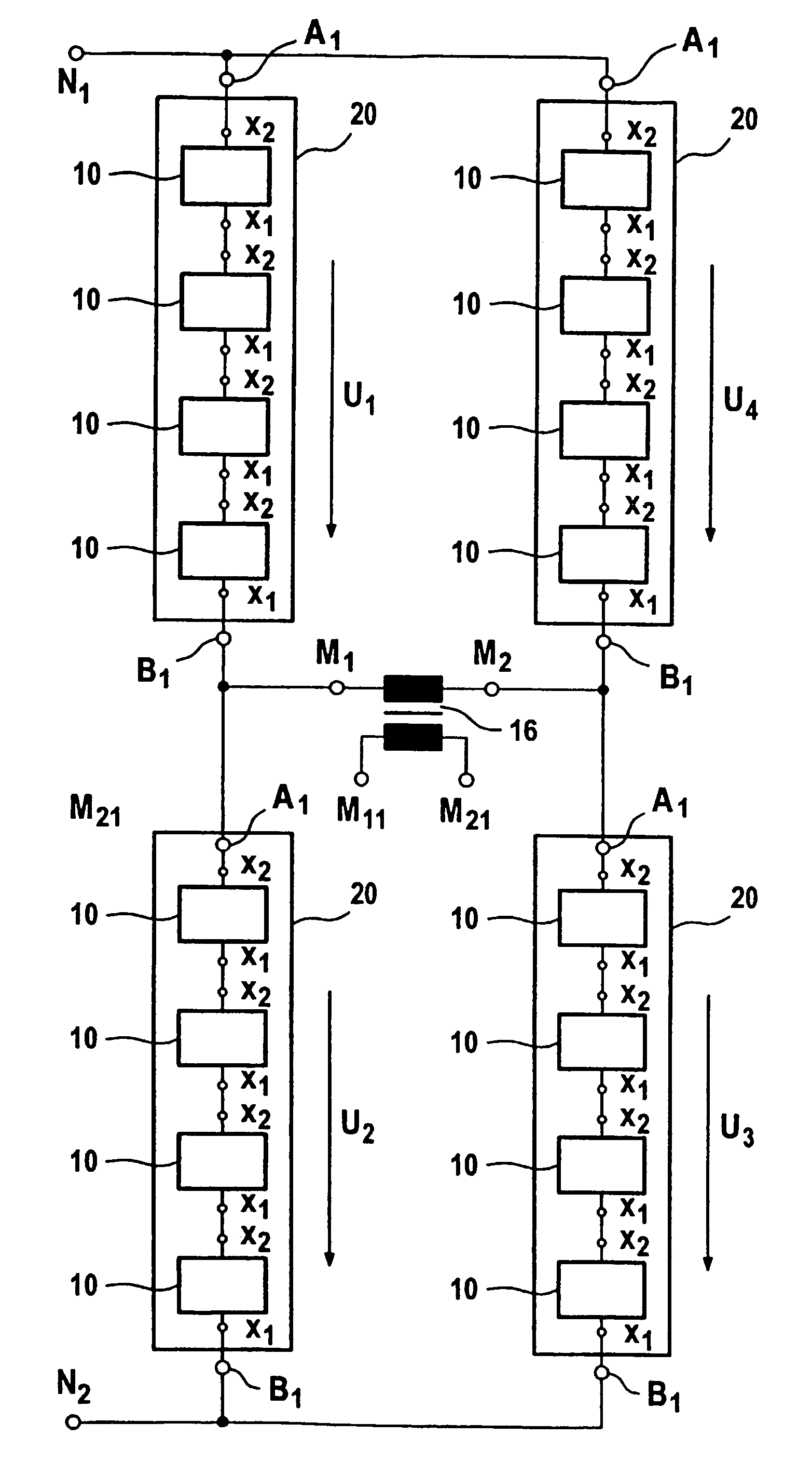
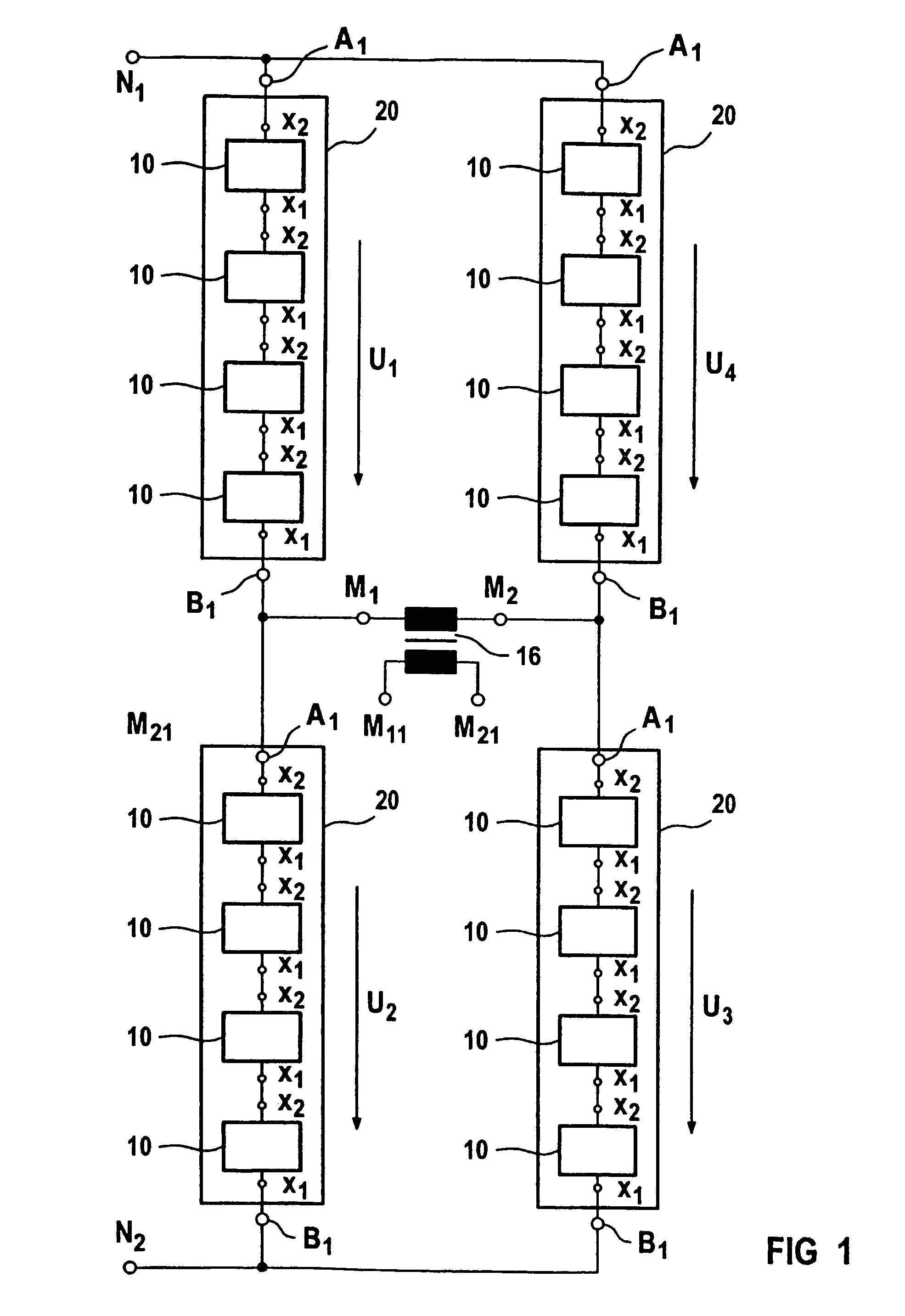
Disadvantageous items relating to this are:In the event of a
short circuit on the AC voltage side between the circuit points N1 and N2 (see FIG. 10), extremely high
discharge currents flow from the
filter capacitor on the AC voltage side, which can cause destruction, owing to the extremely high mechanical forces and / or arc damage that occur.In the event of failure of power semiconductors or a faulty drive, the
discharge current, which is like a
short circuit, can flow directly through the semiconductors, destroying them and their contacts.The very small
stray inductance from the
filter capacitor and from the converter branches which is required for the
semiconductor switches in the matrix converter conflicts increasingly with the rising voltage level (with a
peak value of up to about 50 KV for a 25 KV overhead wire voltage) for a design embodiment which is mechanically resistant to short circuits and is safe in terms of isolation.
Furthermore, there are major impediments to unrestricted spatial arrangement of the components.
However, the
resultant capacitance is still connected in parallel with the network-side connections of the matrix converter, so that the disadvantages also still remain.Additional damping resistors are connected in a known manner in series with the filter capacitors.
This measure results in
high energy losses, although it has become necessary because the filter capacitors are additionally required as snubbers for the IGBTs.The medium-frequency side of the
matrix converters is based on a three-phase design.
However, a staircase voltage that is sufficiently low in
harmonics and has a freely
variable number of voltage steps is still impossible.

