
Bore hole tool assembly and method of designing same

Active Publication Date: 2007-10-09
SHELL OIL CO
View PDF5 Cites 3 Cited by
  • Summary
  • Abstract
  • Description
  • Claims
  • Application Information

AI Technical Summary

Benefits of technology

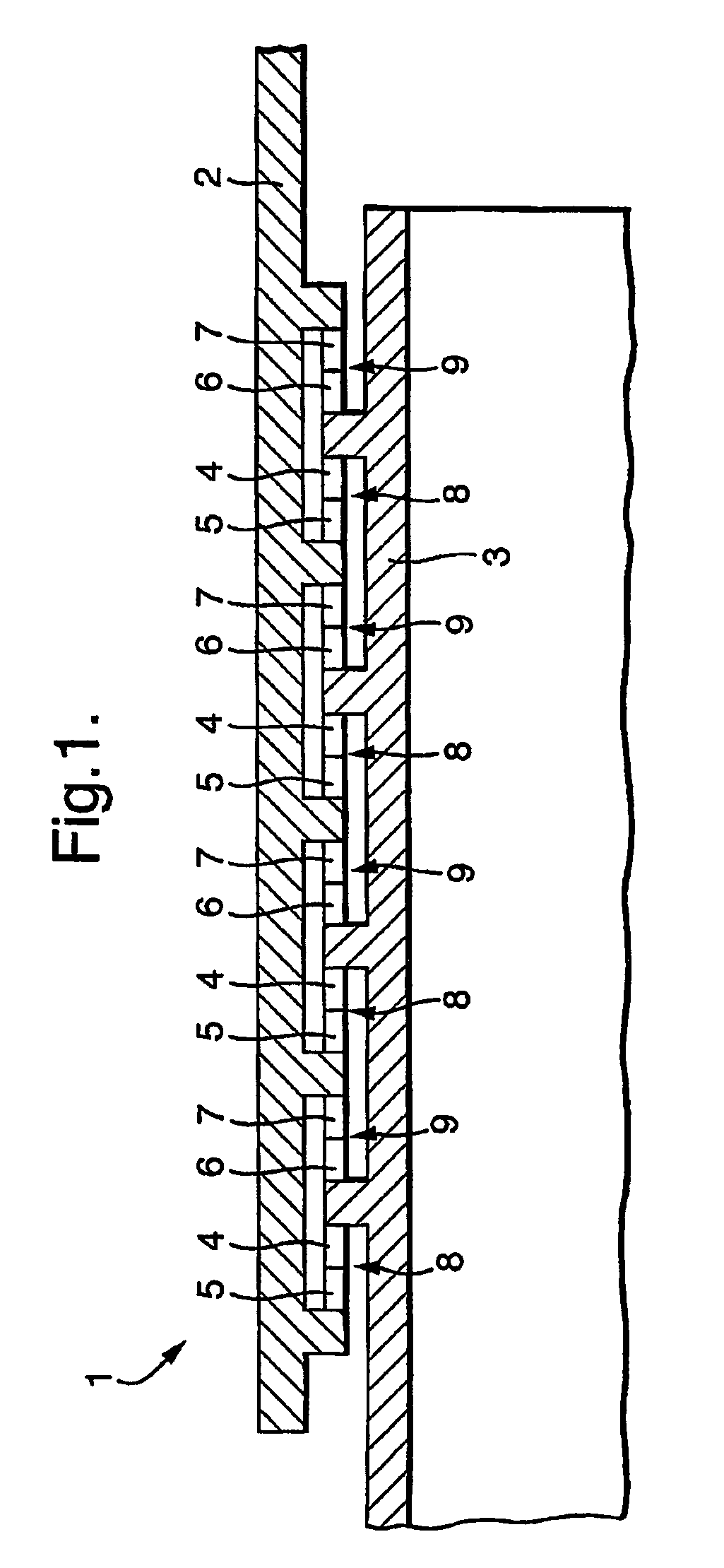
[0020]An advantage of having elastic or elastic and plastic deformable mitigation means is that this allows for elastically biasing the mitigation means against the bearing means which therefore remain operative over a range of loads including medium high loads compared to the maximum allowable load. When also medium high loads are distributed substantially proportionally over the bearing stages, the wear on the bearing means is distributed more evenly over the respective bearing stages and thus the overall lifetime of the entire bearing system is further improved.
[0023]For this reason, the mechanical stiffness of the deformable means in one bearing stage is preferably different in magnitude from that of the deformable means in the other bearing stage. Herewith the axial load transferred by each bearing stage can be re-distributed over the bearing stages as desired, since the relative axial load taken by the bearing stage having the lower mechanical stiffness is lower than it would have been having equal mechanical stiffness as the other bearing stage. Thus by providing the lowest mechanical stiffness in the bearing stage that is otherwise the most heavy loaded, the load is distributed more proportionally over the bearing stages.

Problems solved by technology

These drill strings are subjected to mechanical tension and compression due to the weight of the drill string and friction against the well bore wall.
For instance, the maximum cross section of tubulars for use in a well bore is limited by the need of an annular space between the well bore and the tubulars for allowing sufficient flow of a drilling fluid containing drilled cuttings.
These requirements limit the space available for mounting the bearing assembly in the annular space.
A single bearing stage that fits in the available space may have insufficient strength to bear the load that the bore hole tool assembly is subjected to.
It has been found that, where each bearing stage of the bearing system can transfer a certain maximum static load before failure, the bearing series already fails under a static load that is significantly lower than the mentioned maximum load per bearing stage times the number of bearing stages in the series.
Moreover, under rotary conditions the endurance life of the system is significantly less that would be expected from the specified endurance life of the individual bearings.

Method used


Image

  • Bore hole tool assembly and method of designing same
  • Bore hole tool assembly and method of designing same
  • Bore hole tool assembly and method of designing same

Examples


example

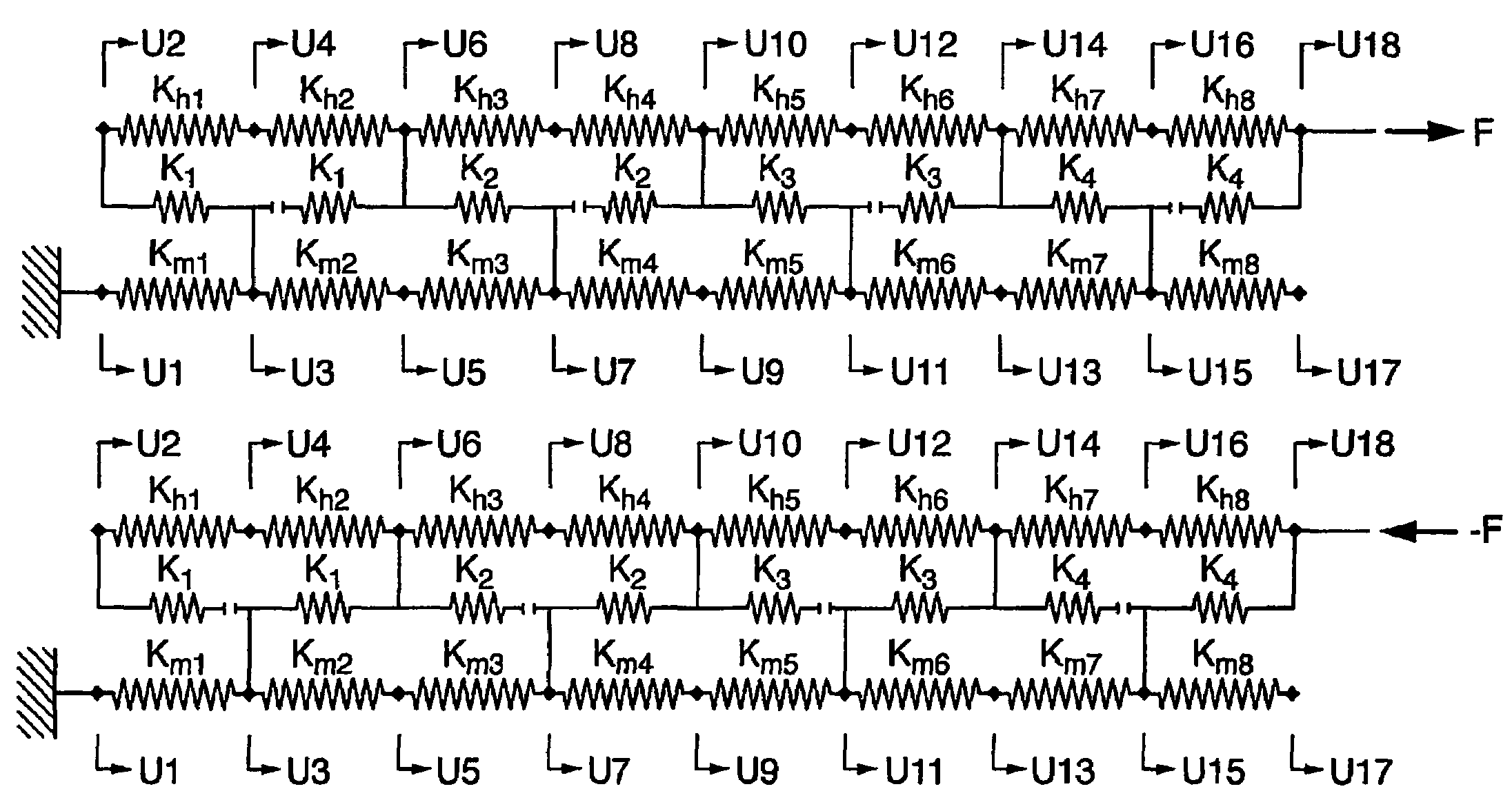
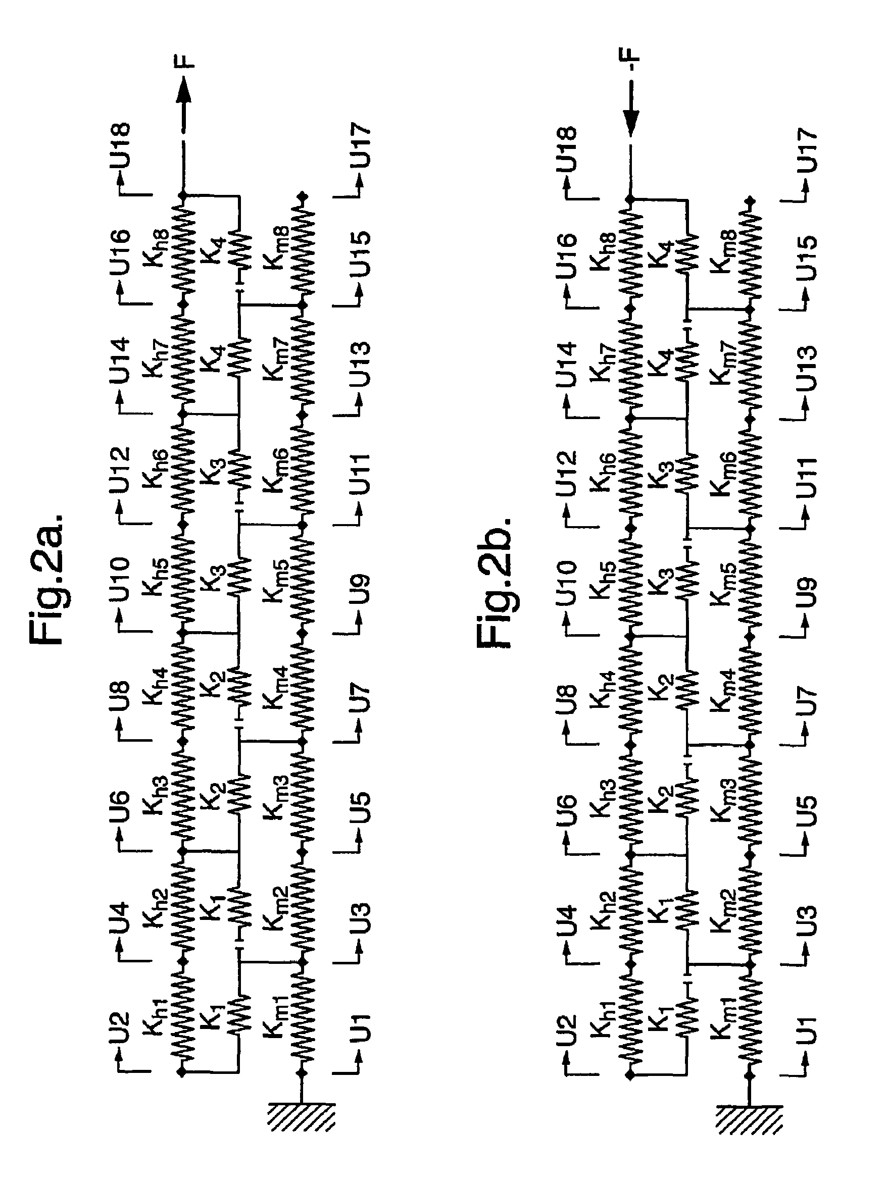
[0082]An oil well drilling tool which is capable of transferring 2000 kN both in tensile as well as in compressive loading is considered. The total force needs to be equally distributed over n=4 bearing stages. In this way the static strength of any of the bearings is not exceeded prematurely and in addition the endurance of the bearing system life is improved. The tool is based on a circular cylindrical mandrel and a circular cylindrical housing.

[0083]The functional specifications for the design put restrictions on the dimensions, in particular the cross sectional areas, of the mandrel and the housing. The mandrel and the housing are made of steel, with an elasticity modulus of Em=Eh=2.1×10⁵ N / mm2. The outer diameter of the housing is restricted to a maximum of 181 mm. The inner diameter of a cylindrical mandrel is restricted to a minimum of 63.5 mm.

[0084]The bearings that are used are thrust bearings have an inner (shaft) diameter of 110 mm, outer (housing) diameter of 145 mm and ...


PUM

PropertyMeasurementUnit
Stiffnessaaaaaaaaaa
Stiffness ratioaaaaaaaaaa

Abstract

A bore hole tool assembly utilizes a multi-stage bearing system deployed between an inner mandrel and an outer tool housing wherein each bearing stage includes bearing element deployed between two deformable elements. The deformable elements are selected, based on the design and material characteristics of the housing, mandrel and bearings, such that tension and compressive loads are distributed proportionally across each bearing stage. A method for calculating loading and the selection of the deformable elements is also disclosed.

Description

[0001]The present application claims priority on European Patent Application 02080230.2 filed 12 Dec. 2002 and European Patent Application 03075523.5 filed 24 Feb. 2003.FIELD OF THE INVENTION[0002]The present invention relates to bore hole tool assembly, in particular for use in a hydrocarbon well bore hole.[0003]In further aspects, the invention relates to a bearing system for use in such a bore hole tool assembly, and to a method of designing such a bore hole tool assembly.BACKGROUND OF THE INVENTION[0004]In oil well drilling and completion operations, a bore hole tool assembly in the form of a tubular drill string is used. These drill strings can consist of various types and sizes of tubular components like drill pipes, heavy weight drill pipe, drill collars, liner, casing and tubing. These components can be used in various configurations.[0005]These drill strings are subjected to mechanical tension and compression due to the weight of the drill string and friction against the we...

Claims


Application Information

Patent Timeline
IPC IPC(8): B21D53/10E21B4/00E21B17/04E21B17/05
CPCE21B17/04E21B17/05Y10T29/497F16C41/02F16C27/04F16C2352/00
Inventor ROGGEBAND, SERGE MATHIEU
Owner SHELL OIL CO
Learn More