
Polymer electrolyte fuel cell, fuel cell electrode, method for producing electrode catalyst layer, and method for producing polymer electrolyte fuel cell

a fuel cell and electrolyte technology, applied in the direction of cell components, final product manufacturing, sustainable manufacturing/processing, etc., can solve the problems of deteriorating discharge performance, affecting the life performance of the cell, and many pinholes or cracks in the catalyst layer, so as to improve the life performance and high production yield , the effect of high quality

Inactive Publication Date: 2007-10-23
PANASONIC CORP
View PDF22 Cites 9 Cited by
  • Summary
  • Abstract
  • Description
  • Claims
  • Application Information

AI Technical Summary

Benefits of technology

The controlled process results in a polymer electrolyte membrane type fuel cell with improved life performance and high production yield, maintaining a minimum lifetime of 5,000 hours without leakage, by minimizing cracking and pinholes in the catalyst layer.

Problems solved by technology

When the polymer electrolyte membrane type fuel cell produced by the related art method has a short lifetime, the catalyst layer has many pinholes or cracking.
Such cracking causes the occurrence of a current density distribution that deteriorates the discharge performance.
Also, the catalyst layer may break off at the cracked area, thereby deteriorating the life performance of the cell.
This agglomeration creates pinholes or cracking in the catalyst layer.

Method used


Image

  • Polymer electrolyte fuel cell, fuel cell electrode, method for producing electrode catalyst layer, and method for producing polymer electrolyte fuel cell
  • Polymer electrolyte fuel cell, fuel cell electrode, method for producing electrode catalyst layer, and method for producing polymer electrolyte fuel cell
  • Polymer electrolyte fuel cell, fuel cell electrode, method for producing electrode catalyst layer, and method for producing polymer electrolyte fuel cell

Examples


example 1

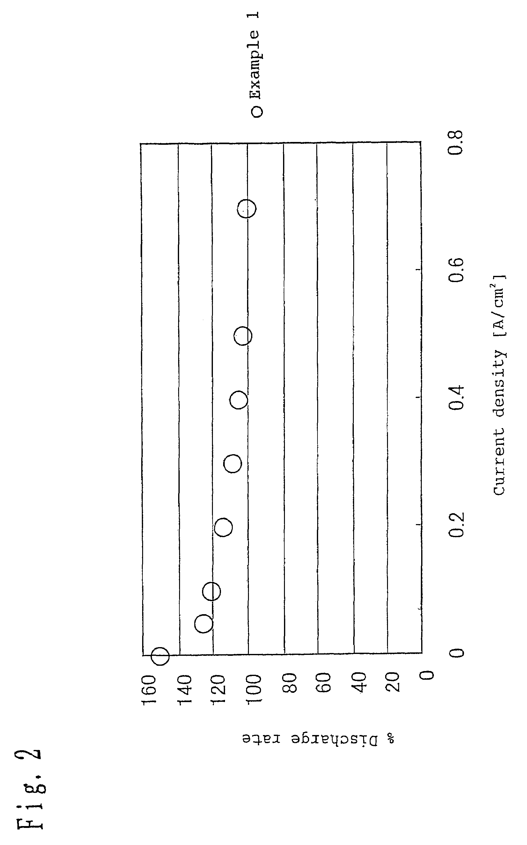
[0078]Referring to a first embodiment of the present invention, a coating compound of catalyst layer was prepared by mixing a catalyst-supporting carbon powder, having 5% by weight of platinum catalyst supported on Ketjen™ black carbon powder, with a composition of a 1 / 1 / 1 mixture of water, isopropyl alcohol and ethylene glycol, as a solvent, using a 5 liter (l) mixer produced by Tokushu Kika Kogyo Co., Ltd. This mixture was mixed with a perfluorosulfonic acid, as a hydrogen ionically-conductive agent, and binder in an amount of 80% based on the carbon component of the carbon powder to prepare an anode catalyst paste having a solid content concentration of 20 wt %.

[0079]Subsequently, the catalyst paste was spread over a polymer film made of polyethylene terephthalate, having a thickness of 50 μm, and then dried at a drying rate of 2.5 mg / cm2·min to form a catalyst layer to a thickness of 10 μm. The catalyst layer was then bonded to one side of a polymer electrolyte membrane to prepa...

example 2

[0083]A fuel cell was prepared in the same manner as in Example 1 except that the drying rate was 10 mg / cm2·min.

example 3

[0084]A fuel cell was prepared in the same manner as in Example 1 except that the drying rate was 20 mg / cm2·min.


PUM

PropertyMeasurementUnit
thicknessaaaaaaaaaa
diameteraaaaaaaaaa
volume resistivityaaaaaaaaaa

Abstract

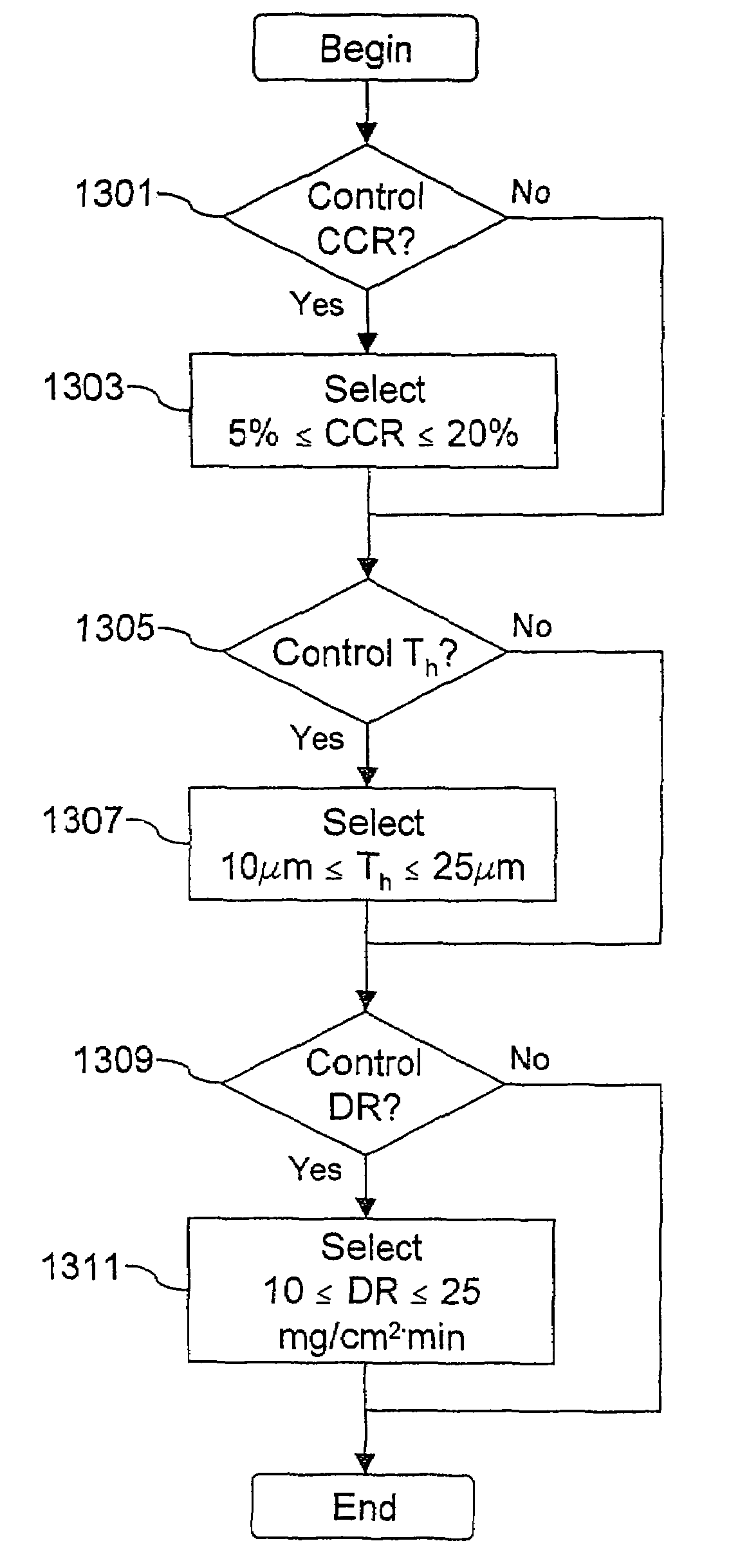
A method for producing a polymer electrolyte membrane type fuel cell including a polymer electrolyte membrane, fuel and air electrodes that sandwich therebetween the polymer electrolyte membrane and that each include a gas diffusion layer and a catalyst layer provided in contact with the polymer electrolyte membrane, and separators provided in contact with the gas diffusion layers. A paste containing at least a carbon powder having a catalyst supported thereon is spread over a predetermined support, and the coated support is dried to form the catalyst layer. A cracking occupation area on the electrodes is controlled to a predetermined tolerance by controlling at least one of (1) a thickness of the catalyst layer, (2) a kind of carbon having the catalyst supported thereon, and (3) a drying rate of a solvent of the paste.

Description

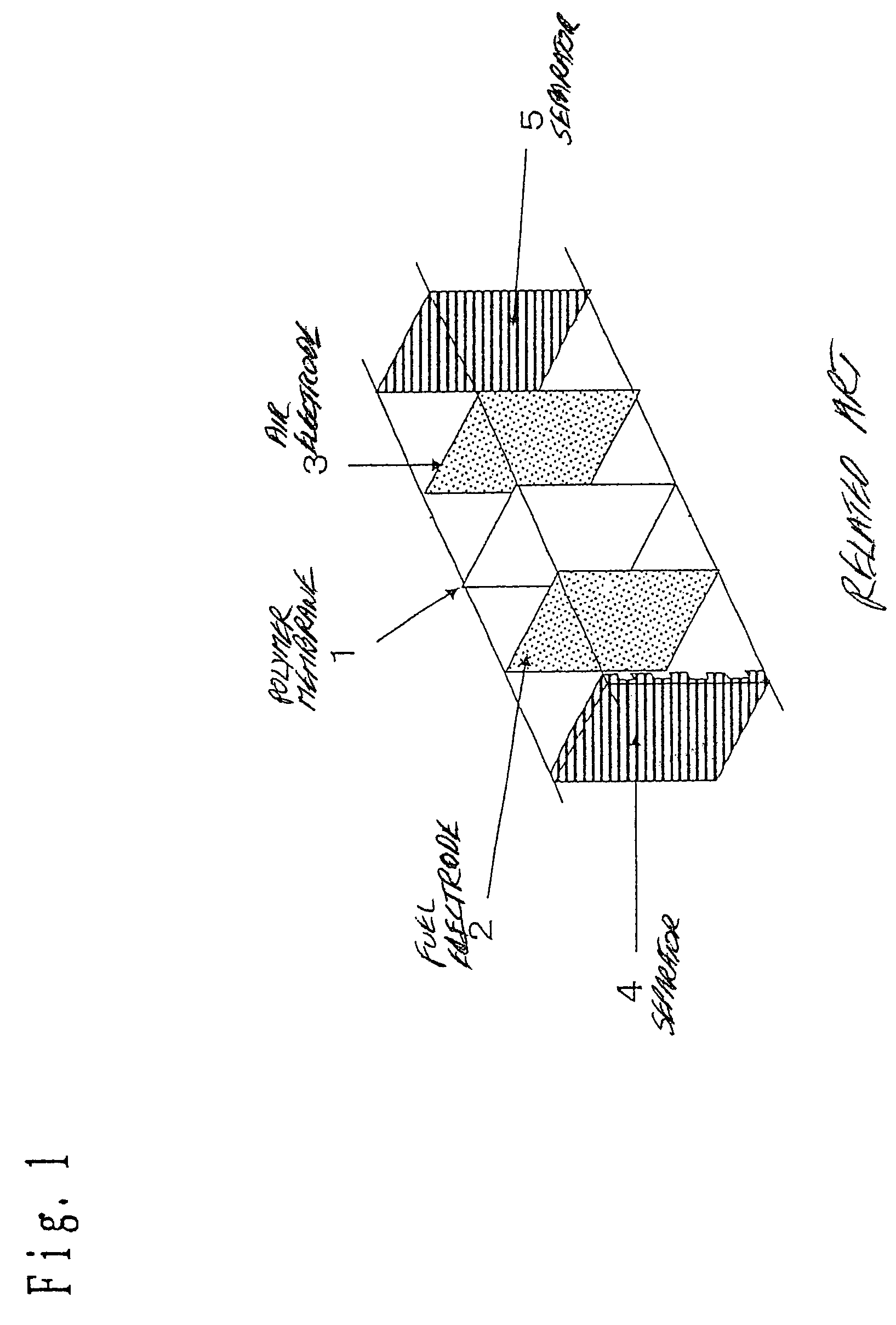
[0001]This application is a continuation-in-part of PCT / JP03 / 02973 filed Mar. 13, 2003.TECHNICAL FIELD[0002]The present invention relates to polymer electrolyte membrane type fuel cells and methods of making such fuel cells.RELATED ART[0003]Operation of a fuel cell involves an electrochemical reaction of a fuel gas with an oxidizer gas containing oxygen, such as air, to generate electric power energy. A polymer electrolyte type fuel cell is one kind of fuel cell. An example of a single cell constituting a polymer electrolyte type fuel cell is shown in FIG. 1.[0004]In FIG. 1, the single cell includes a polymer membrane 1 that is used as a hydrogen ionically-conductive membrane, a fuel electrode 2 including a catalyst layer and a gas diffusion layer that is formed by a carbon sheet and a water-repellent layer, an air electrode 3 including a gas diffusion layer and a catalyst layer which are similar to those of fuel electrode 2, and separators 4 and 5 that act to prevent mixing of hydr...

Claims


Application Information

Patent Timeline
Patent Type & Authority Patents(United States)
IPC IPC(8): H01M4/00B05D5/12H01M8/10H01M4/86H01M4/88H01M4/92H01M4/96
CPCH01M4/8605H01M4/8828H01M4/8882H01M4/926H01M4/96H01M8/1004H01M4/92Y02E60/522Y02P70/50Y02E60/50H01M4/88H01M8/02H01M8/10
Inventor UEYAMA, YASUHIROWATANABE, MASARUKAMIKIHARA, NOBUYUKIYASUMOTO, EIICHI
Owner PANASONIC CORP
Learn More