
Inorganic contaminant removal from water

a technology of inorganic ionic species and water supply, applied in the direction of water/sludge/sewage treatment, specific water treatment objectives, solid sorbent liquid separation, etc., can solve the problem of significant risk of breakthrough and chromatographic peaking events, and the method of using such particulate ion exchange resins is not disclosed

Active Publication Date: 2007-11-06
IXOM OPERATIONS
View PDF133 Cites 30 Cited by
  • Summary
  • Abstract
  • Description
  • Claims
  • Application Information

AI Technical Summary

Problems solved by technology

Water supplies for drinking water often contain unacceptably high levels of inorganic ionic species.
None of these publications disclose methods for using such particulate ion exchange resins for removal of inorganic ionic species down to acceptable levels, which are often in the range of parts-per-billion for drinking water.
Removal of contaminating inorganic anions by ion exchange in the presence of competing ions such as sulfate, nitrate, bicarbonate and dissolved organic compounds present in the water has not heretofore been widely adopted primarily because the competing ions exhaust the resin before significant amounts of the target inorganic anions (e.g., arsenate) have been removed, or because unless the contact time between the water and resin is carefully calibrated and constantly readjusted to account for small concentration differences, there is a significant risk of breakthrough and chromatographic peaking events.
Thus, frequent regeneration of the resin and the need for careful monitoring of the process can make removal of such contaminating ions by means of ion exchange resins too difficult to operate to be viable.
When silicate is present as a competing ion, fouling of the ion exchange resin is a severe problem in inorganics removal by means of ion exchange columns.
In such cases, it is believed that the resin particles become coated with polymerised silicate, leading to an impenetrable layer of solid material on and near the surface of the bed, resulting in the columns becoming inoperable for inorganic ionic species removal.

Method used


Image

  • Inorganic contaminant removal from water
  • Inorganic contaminant removal from water
  • Inorganic contaminant removal from water

Examples


example 1

Arsenic V Trial

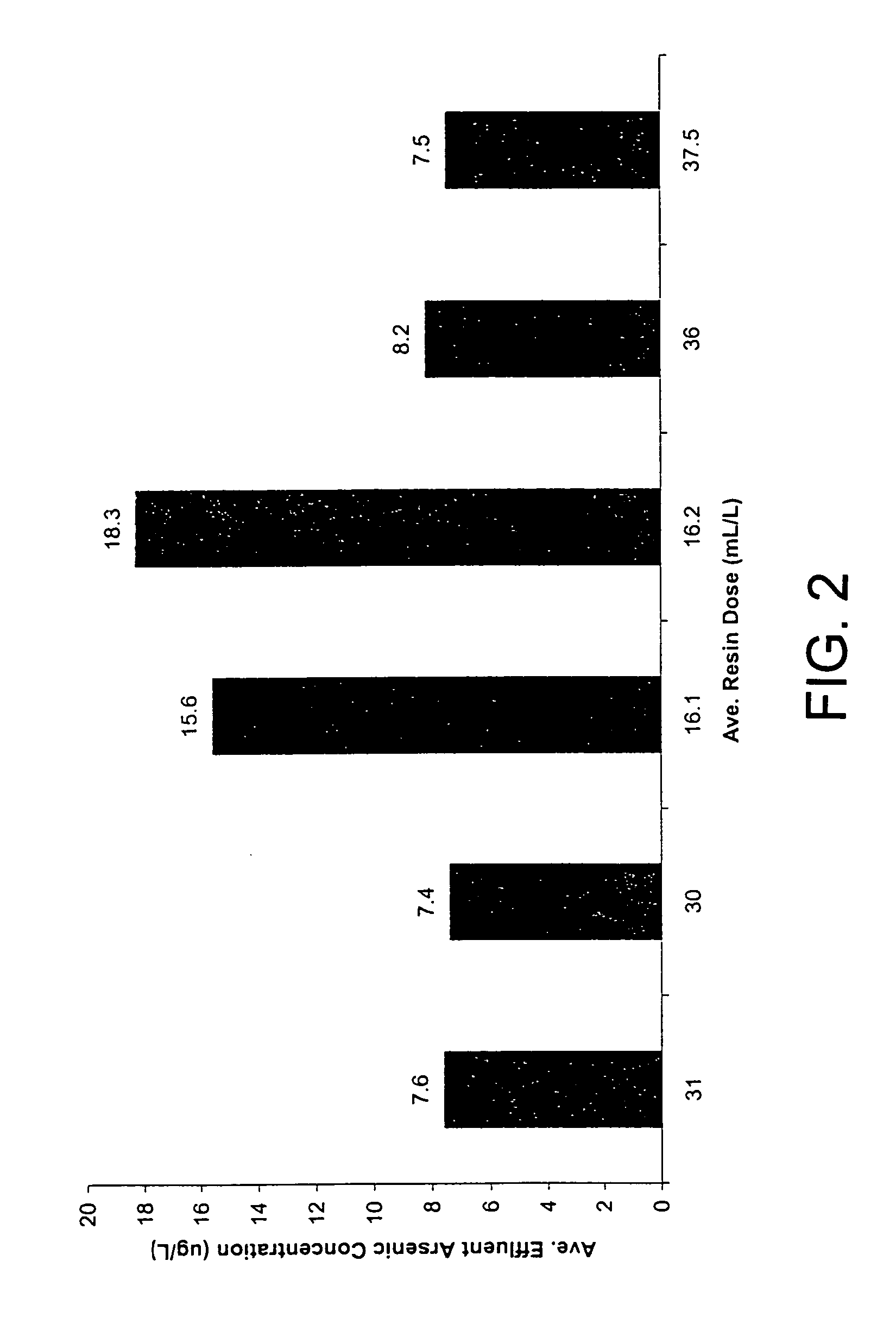
[0095]A trial was undertaken to assess arsenic removal from a water under continuous flow conditions of raw water containing a stable influent arsenic level in the range of 49.9 to 54.2 μ / L arsenic, predominantly as arsenic V, with a silica background in the water of around 100 to 110 μg / L and a sulfate background of about 12 to 15 mg / L. The water processing facility in which the test was conducted uses ground water having a daily capacity of 4 million gallons per day (MGD). It currently does not apply any form of pre-treatment before delivering water to the distribution system. New contaminant guidelines require a maximum of 10 μg / L total arsenic for drinking water.

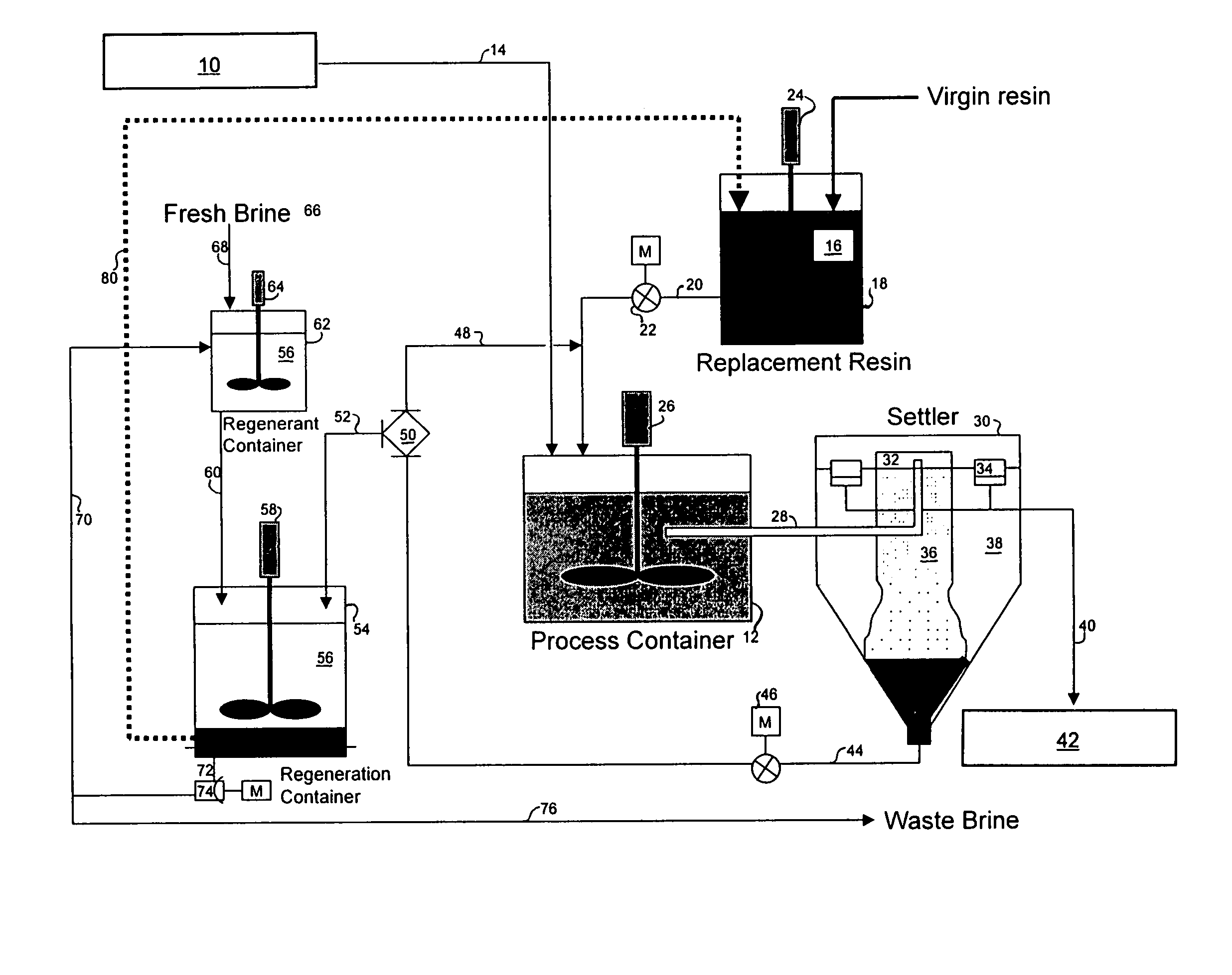
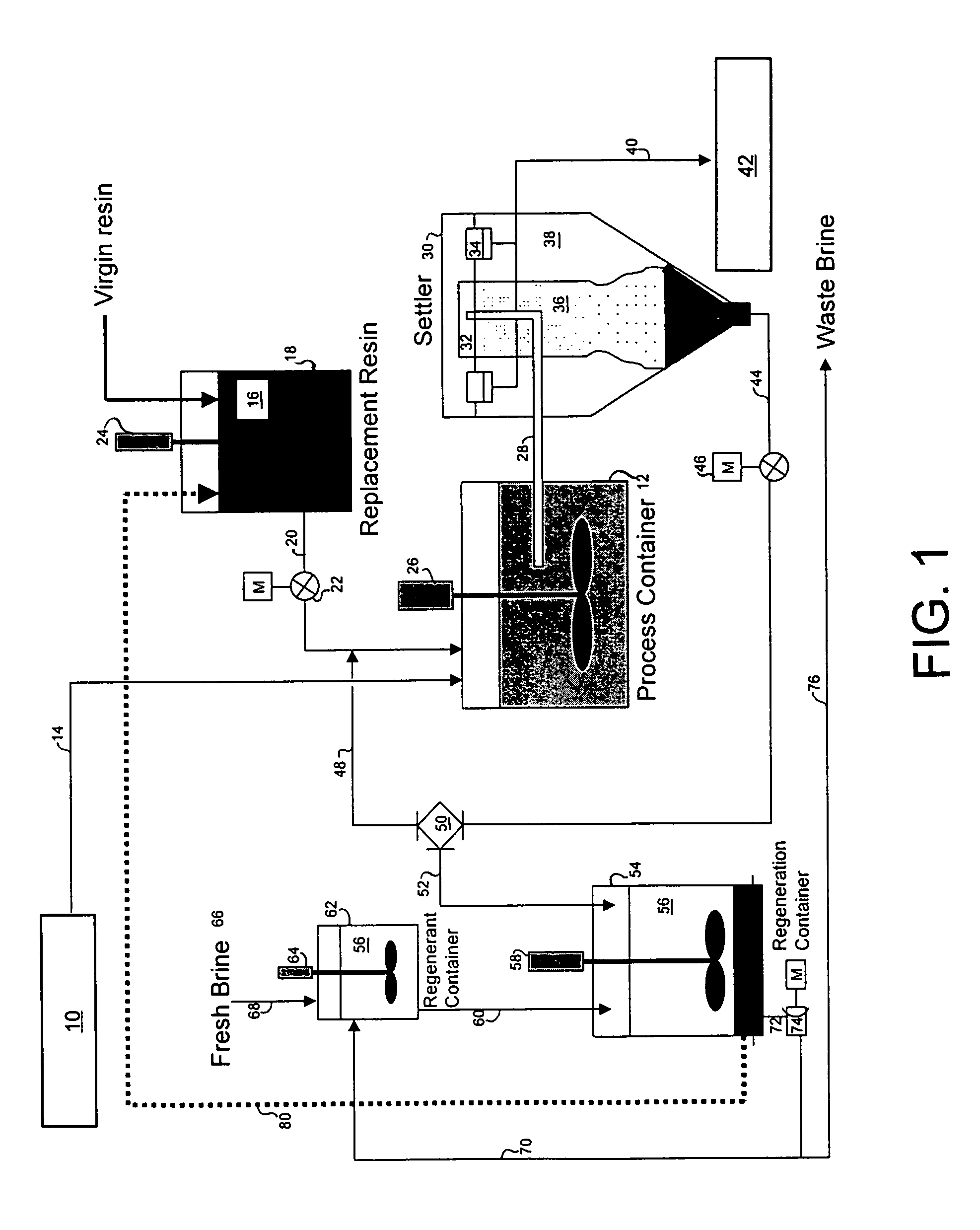
[0096]A three-week trial was undertaken to demonstrate the ability of the magnetic resin process of this invention to remove arsenic from the ground water supply down to a level of 10 μg / L or less. The trial was conducted using a two-gallon-per-minute (2 GPM) pilot plant set-up similar to that shown in FIG...

example 2

Perchlorate Removal from Surface Water

[0106]Influent water in this trial was drawn directly from a surface water source. The trial was conducted using a 10 GPM magnetic resin pilot plant similar to that shown in FIG. 1. The water contained perchlorate in quantities ranging from 2.5 to 3.6 μg / L.

[0107]Resin dose was varied between 20 and 50 mL / L. Contact time and regeneration rate were held constant for the majority of the trial at 30 minutes and 10% respectively.

[0108]The capability of the magnetic resin process to remove perchlorate from this water was demonstrated. Results showed that removal efficiencies of 50% are achievable under the operating conditions applied during this trial; and perchlorate removal efficiency increases with increasing resin dose.

[0109]There was a high level of background sulfate in the water, typically in excess of 200 mg / L.

[0110]Removal efficiencies do not stabilize until the process has been running for some time. In this pilot plant setting, the entire ...

example 3

Chromium (VI) Trial

[0127]The groundwater tested was from wells that typically contain less than 10 μg / L total chromium. Water for this trial was spiked with 100 μg / L chromium (VI). The magnetic resin process was trialed using a 2 GPM pilot plant over a three week period. Flow rates varied from 0.5-1 GPM. Resin doses were varied between 10 and 60 mL / L, contact times between 15 and 40 minutes, and regeneration rates between 6% and 18%.

[0128]The magnetic resin trial can be divided into three sections (see FIGS. 5 to 7). For Samples 1 through 21, the resin dose was varied between 10 and 32 mL / L, the contact time between 15 and 40 minutes and the regeneration rate between 6% and 18%. In this period, the effectiveness of the magnetic resin process was variable, removing between 50% and 88% Cr (VI). For Samples 22 through 26, constant conditions of 40 mL / L resin dose, 35 min. contact time and 16% regeneration rate were applied. In this region, removal was consistently above 88% with an ave...


PUM

PropertyMeasurementUnit
concentrationaaaaaaaaaa

Abstract

A method is provided for removing an inorganic ionic species or organometallic ion contaminant, or combination contaminants, including such as arsenic, chromium, bromide, bromate, perchlorate, and / or others from water which contains an unacceptably high concentration of the contaminant(s). The method includes treating the water with an ion exchange resin, preferably a magnetic ion exchange resin such as MIEX® Resin, which is capable of adsorbing the inorganic ionic species contaminant(s), and regenerating and recycling the ion exchange resin back to the process. The method produces potable water from ground water containing such contaminants and eliminates breakthrough and chromatographic peaking problems observed with conventional ion exchange systems.

Description

CROSS-REFERENCE TO RELATED APPLICATIONS[0001]This application claims benefit of U.S. Provisional Patent Application No. 60 / 568,972, filed May 7, 2004.BACKGROUND OF THE INVENTION[0002]The present invention relates to water treatment, in particular to a process for the removal of inorganic contaminants from water.[0003]Water supplies for drinking water often contain unacceptably high levels of inorganic ionic species. These inorganic ionic species include anions such as perchlorate, nitrate, bromide and bromate, other anions such as species containing arsenic V, arsenic III and chromium, as well as other inorganic anions known to the art to be removable by anion exchange agents; and inorganic cations such as ions of calcium, copper, nickel, magnesium, lead, mercury, cadmium and beryllium, and other inorganic ionic species known to the art to be removable by cation exchange agents.[0004]Water containing such undesirable inorganic ionic species also often contains ions which compete wit...

Claims


Application Information

Patent Timeline
Patent Type & Authority Patents(United States)
IPC IPC(8): B01D15/04
CPCB01J20/28009B01J39/04B01J41/04B01J47/001B01J49/00C02F2303/16C02F2001/422C02F2001/425C02F2101/20B01J47/011
Inventor BOURKE, MICHAEL FRANCISNGUYEN, HUNG VAN
Owner IXOM OPERATIONS
Learn More