Carbon dioxide snow apparatus

a carbon dioxide snow and apparatus technology, applied in lighting and heating apparatus, combustion types, cleaning using liquids, etc., can solve the problems of not teaching an apparatus for generating and controlling such a cleaning spray, not teaching providing in-situ spray cleaning of excimer laser processed substrates, entrainment and deposition of atmospheric contaminants on substrate surfaces, etc., to improve jetting, reduce clogging and sputtering, and increase joule-thompson cooling

Active Publication Date: 2007-11-13
COOL CLEAN TECH
View PDF52 Cites 39 Cited by
  • Summary
  • Abstract
  • Description
  • Claims
  • Application Information

AI Technical Summary

Benefits of technology

[0016]The carbon dioxide snow apparatus of the present invention generally includes a snow generation subsystem and a diluent or propellant subsystem connected to a delivery line and applicator. The snow generation subsystem includes a stepped capillary condenser comprising at least two connected segments of differing diameters. The stepped capillary condenser provides increased Joule-Thompson cooling in the conversion of liquid carbon dioxide to solid carbon dioxide, reduces clogging and sputtering, improves jetting, and allows for greater spray temperature control. Moreover, the stepped capillary condenser produces coarser particles than a single step capillary.

Problems solved by technology

Due to there inherent incompatibilities with process tools, the aforementioned methods are typically performed as a step before or after a manufacturing tool or process.
However, in practice, entrainment and deposition of atmospheric contaminants onto substrate surfaces being treated with the cryogenic spray is resulted.
However, the '873 invention does not teach an apparatus for generating and controlled such a cleaning spray.
More importantly, '873 does not teach providing in-situ spray cleaning of Excimer LASER processed substrates and does not provide a means for integrating cryogenic spray cleaning into the LASER production process.
The failure in the prior art to effectively provide a technology capable of operating within the production process, the same workcell or process tool to provide clean-in-place capability results in a number of disadvantages and limitations in manufacturing operations.
As discussed herein, overall productivity is limited by many factors including environmental control challenges for cryogenic spray cleaning, carbon dioxide cleaning machine's ability to operated autonomously, adaptability to different manufacturing processes and tools, cleaning complex surfaces, and cleaning multiple surfaces at one time.
This is particularly disadvantageous in flexible manufacturing systems in which the entire machining operation is intended to be completely automated.
Flexible manufacturing systems are designed to operate without human assistance, or greatly reduced human assistance, and it substantially limits their efficiency if a worker must regularly remove substrates, clean them and return them to the manufacturing tool or line.
Moreover, fine particles require extremely high velocities to dislodge tenacious surface contaminants.
The growing variety and complexity of matrix array packages present a true challenge to many back end processes.
Quality issues associated with conventional dicing of such devices using water-based coolant include chipping along the edges of the diced kerf, smearing of the ductile copper, and the formation of burrs.
No prior art teaches a module which combines all the necessary elements for efficient use of solid phase carbon dioxide spray cleaning in production tools and on the manufacturing line.
Segregation of the cleaning process has been due to the inherent chemical and physical incompatibilities between conventional cleaning operations and most assembly tools.

Method used


Image

  • Carbon dioxide snow apparatus
  • Carbon dioxide snow apparatus
  • Carbon dioxide snow apparatus

Examples


Embodiment Construction

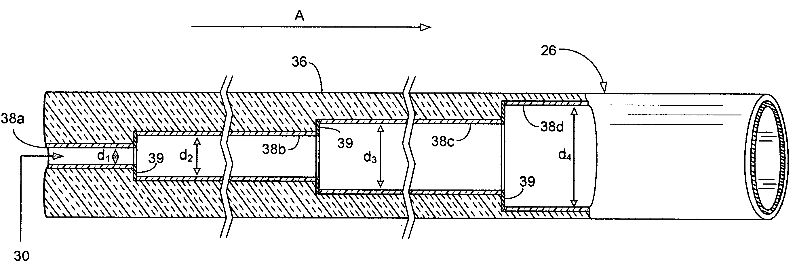
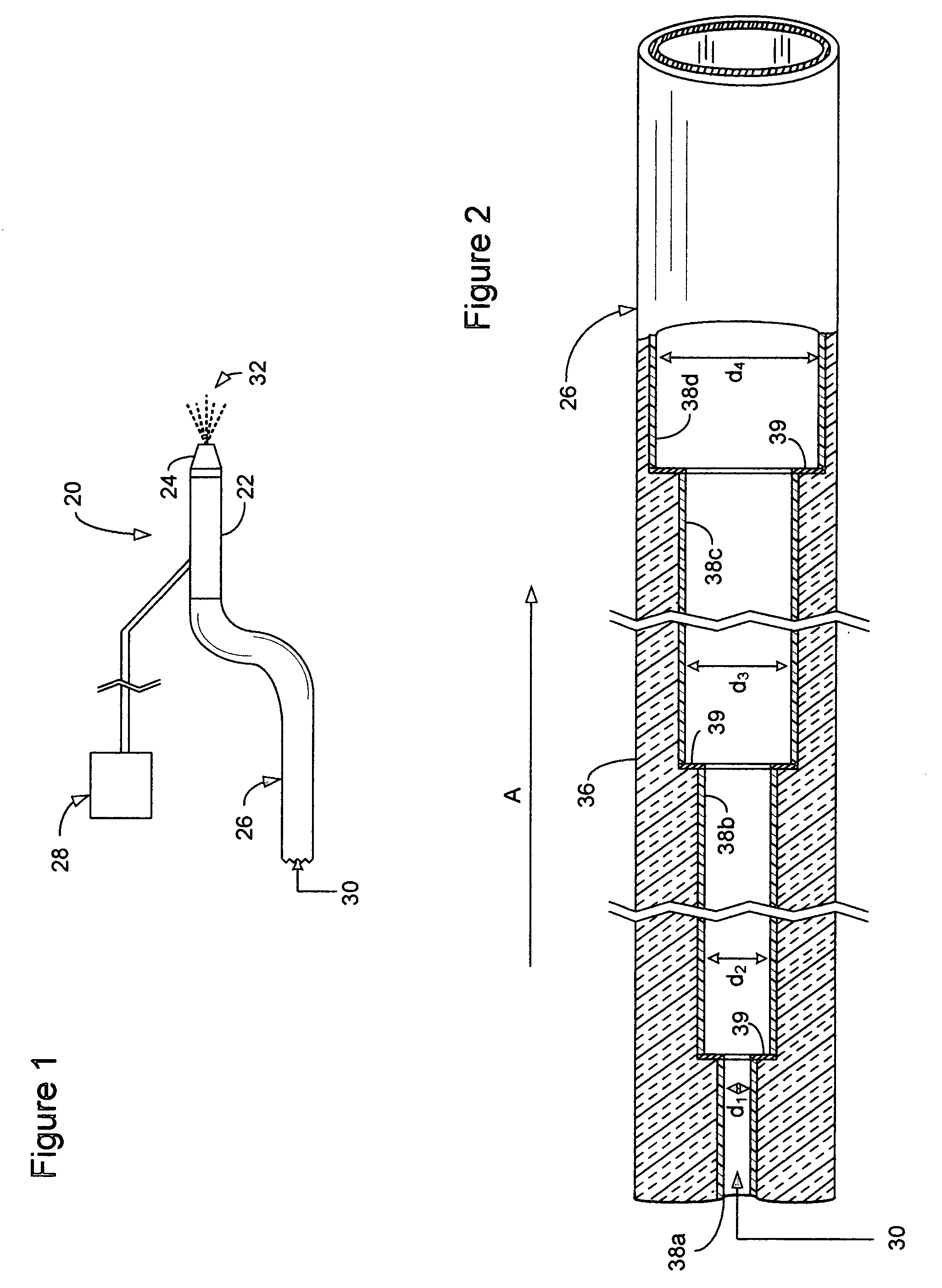
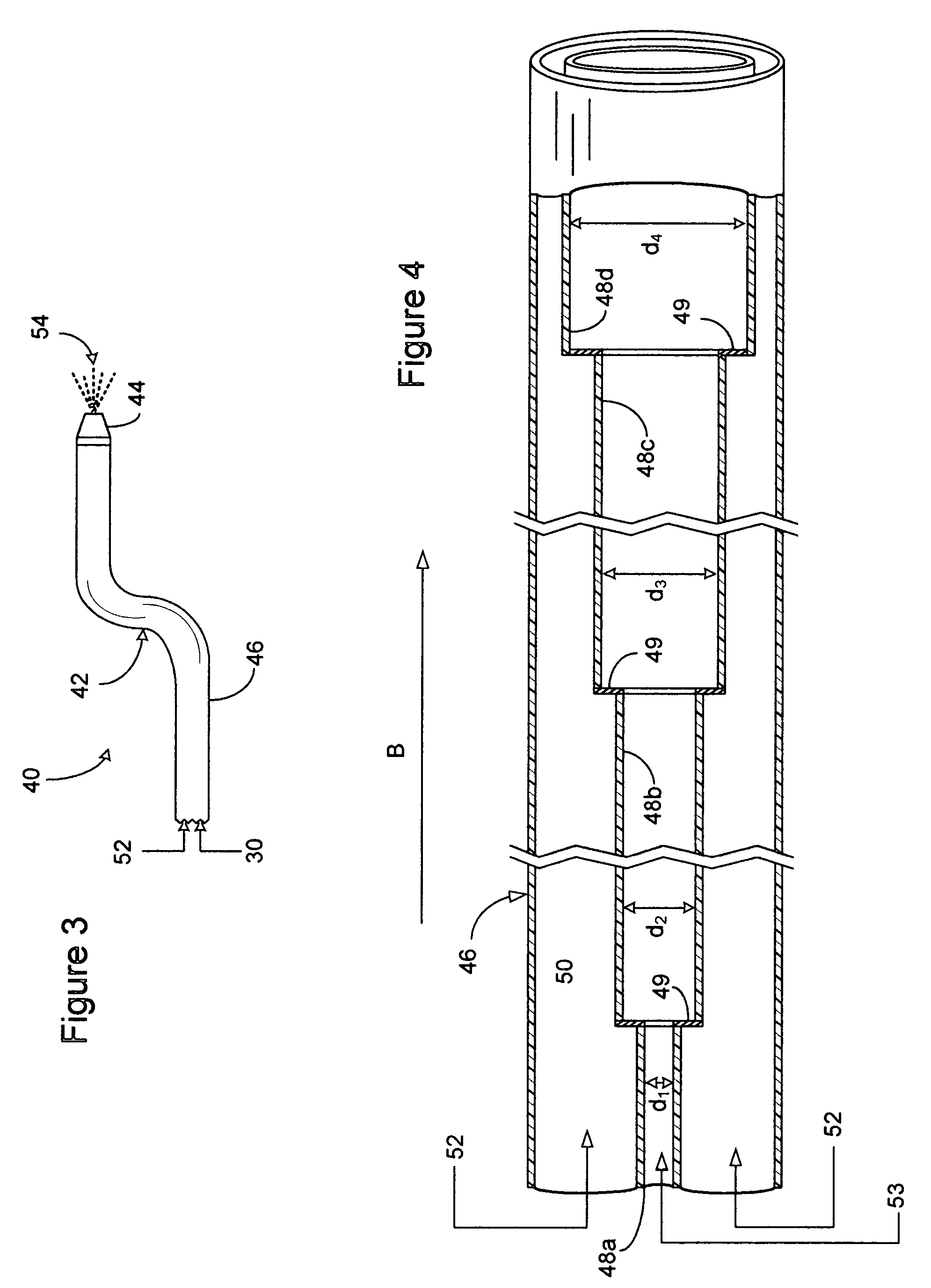
[0033]A carbon dioxide snow treatment apparatus for selectively treating a substrate within a manufacturing process is generally indicated at 20 in FIG. 1. The apparatus 20 includes a dense fluid spray applicator 22, with a mixing spray nozzle 24, connected to a flexible capillary condenser 26. Preferably, the dense fluid spray applicator 22, used in conjunction with a connected propellant gas source, is either a co-axial dense fluid spray applicator as taught by the present inventor and fully disclosed in U.S. Pat. No. 5,725,154 or a tri-axial type delivering apparatus as taught by the present inventor and fully disclosed in U.S. Provisional Application No. 60 / 726,466, both of which are hereby incorporated herein by reference. Employing either fluid spray applicator 22, a dense fluid 30, preferably liquid carbon dioxide, enters the capillary condenser 26 whereupon passing therethrough, or in conjunction with the applicator 22, is condensed and solid carbon dioxide snow 32 exits the...


PUM

PropertyMeasurementUnit
inner diameteraaaaaaaaaa
lengthaaaaaaaaaa
diametersaaaaaaaaaa

Abstract

A carbon dioxide snow apparatus of the present invention includes a carbon dioxide snow generation system and a propellant generation system connected to a common carbon dioxide gas source. The carbon dioxide snow generation system includes a condenser having a at least two connected segments, wherein a first segment has a lesser diameter than the a second segment to provide a stepped expansion cavity for cooling and condensing liquid carbon dioxide into solid carbon dioxide snow. Several snow generation systems, each separately controllable with separate condensers, may be integrated with the propellant generation system and common carbon dioxide source to provide for a multiplicity of carbon dioxide snow applicators for integration into both manual and automated machining processes.

Description

CROSS-REFERENCE TO RELATED APPLICATION(S)[0001]This application claims the benefit of U.S. Provisional Patent Application No. 60 / 635,230 entitled METHOD AND APPARATUS FOR SELECTIVE CLEANING AND TREATMENT WITHIN A MANUFACTURING PROCESS filed on 13 Dec. 2004 and which is hereby incorporated herein by reference.BACKGROUND OF INVENTION[0002]The present invention generally relates to manufacturing tools and procedures. More specifically, the present invention relates to a precision cleaning apparatus and process that can be integrated directly into various manufacturing tools and processes. Manufacturing tools and processes requiring precision cleaning include, among others, die attachment, machining, board cutting, wafer singulation, assembly, rework, inspection, wire bonding, adhesive bonding, soldering, underfilling, dispensing, sealing, dicing, coating and trimming tools. These tools may be designed and developed as stand-alone tools, located on automation lines or integrated into ex...

Claims


Application Information

Patent Timeline
Patent Type & Authority Patents(United States)
IPC IPC(8): B08B3/02
CPCB24C1/003B24C11/005B24C5/02
Inventor JACKSON, DAVID P.
Owner COOL CLEAN TECH
Why Eureka
Try Eureka