Liquid crystal display cell, display cell, glass substrate for display device and manufacturing method for liquid crystal display cell

a technology of liquid crystal display and glass substrate, which is applied in the direction of thin material processing, instruments, chemistry apparatus and processes, etc., can solve the problems of reduced glass substrate strength, difficult handling, and deformation of thin glass substrate, so as to reduce the physical strength of glass substrate, simplify manufacturing steps, and reduce the weight of display cells

Inactive Publication Date: 2007-11-13
INT BUSINESS MASCH CORP +1
View PDF13 Cites 13 Cited by
  • Summary
  • Abstract
  • Description
  • Claims
  • Application Information

AI Technical Summary

Benefits of technology

[0010]That is, an object of the invention is to restore the light transmittance of a glass substrate whose surface roughness is increased by a polishing operation and to provide a liquid crystal display cell employing such a glass substrate.
[0011]Furthermore, another object of the invention is to enhance the strength of a glass substrate whose thickness is reduced by a polishing operation and to provide a liquid crystal display cell employing a glass substrate whose strength is enhanced.
[0016]A difference between the refractive index of the glass substrate and the refractive index of the metal oxide glass film can be within plus / minus 0.02. A combination of the glass substrate and metal oxide glass film covering the outer surface of the glass substrate exhibits high transmittance of light.
[0017]The metal oxide glass film covering the outer surface of the glass substrate can be formed by hydrolyzing a metal alkoxide composition coated on the outer surface of the glass substrate. A glass-like film is formed on the surface of the glass substrate, on which surface a number of projections and depressions are formed by a physical or chemical technique. The surface is then flattened, which eliminates scattering of light at an interface between the glass substrate and metal oxide glass film and restores the glass substrate to have approximately a 100% light transmittance.
[0020]Furthermore, a display cell according to another embodiment of the invention includes a glass substrate having a thickness reduced by a thinning process, and a sol-gel layer having organic polysiloxane as a primary constituent and formed on a surface of the thinned glass substrate, the thinned substrate being produced by the thinning process. The sol-gel layer of the display cell both reduces the weight of the display cell and compensates for the reduced physical strength of the glass substrate. Moreover, in the thinning process, the surface of the glass substrate roughened by rough polishing can be flattened without the finishing processing such as polishing, thereby simplifying the manufacturing steps.
[0021]To form a sol-gel layer on the surface of the thinned glass substrate, the hydrolyzation of organic polysiloxane is preferably provided at a temperature of not greater than 80 degrees C. Even when a liquid crystal is enclosed between the glass substrates, the hydrolyzation provided at such a relatively low temperature prevents the liquid crystal enclosed between the substrates from being thermally changed and thereby reducing the weight of the display cell. Moreover, the curing agent used in the hydrolyzation is preferably chosen from an organic tin compound or boron halide.

Problems solved by technology

A thin glass substrate has degraded strength and is difficult to handle.
However, because the reduced glass substrates have its strength reduced, the glass substrates may break more easily during the finishing polishing step.
For example, a problem arises when the substrate is reduced to a thickness not greater than 0.3 mm.
Furthermore, the polishing operation causes micro-cracks to appear on the surfaces of the glass substrates, potentially reducing the physical strength.
Further, bending, deflection, deformation caused by changes in temperature, and the like have to be taken into account, and therefore, the productivity of liquid crystal display device may suffer because of the reduced thickness.

Method used


Image

  • Liquid crystal display cell, display cell, glass substrate for display device and manufacturing method for liquid crystal display cell
  • Liquid crystal display cell, display cell, glass substrate for display device and manufacturing method for liquid crystal display cell
  • Liquid crystal display cell, display cell, glass substrate for display device and manufacturing method for liquid crystal display cell

Examples


first embodiment

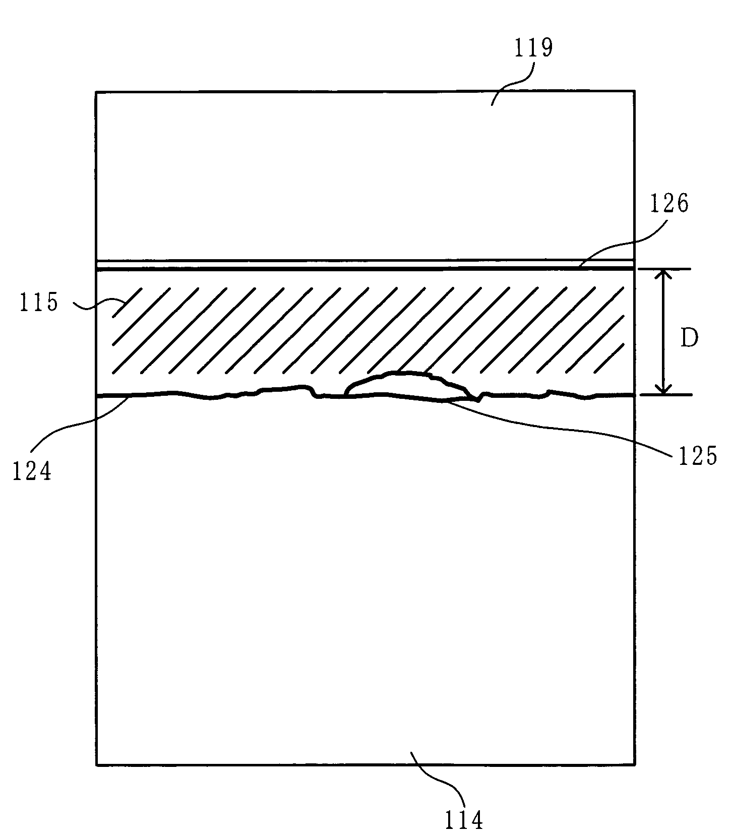
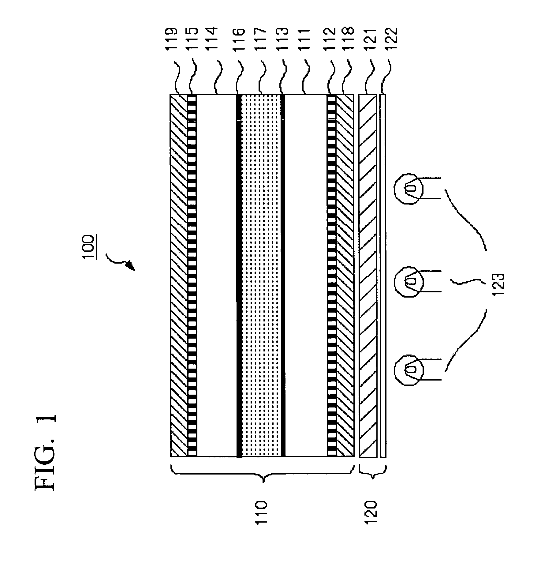
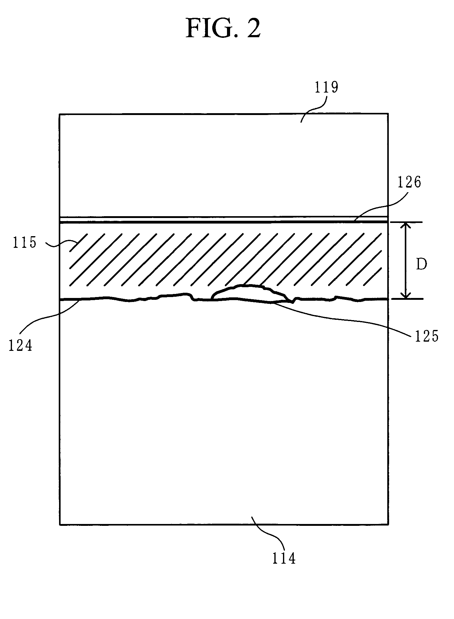
[0028]FIG. 1 is a diagram of a liquid crystal display cell according to an embodidment of the invention. A liquid crystal display device 100 shown in FIG. 1 includes: a liquid crystal display cell 110 including a lamination of a lower polarizer 118, a first glass substrate 111 having a metal oxide glass film 112 formed on the side of the lower polarizer 118, a liquid crystal layer 117, a second glass substrate 114 having a metal oxide glass film 115 formed on the side opposite the liquid crystal layer 117, and an upper polarizer 119; and a backlight unit 120 including a light guide plate 121, a diffusion plate 122, and light sources 123. The liquid crystal layer 117 is configured so that peripheral portions of the first glass substrate 111 and second glass substrate 114 are sealed with a sealant (not shown) and the layer includes a liquid crystal filled in a space formed by a prescribed gap. Though not shown, a plurality of optical compensation films designed to enhance scattering o...

second embodiment

[0042]A second embodiment is applied to a liquid crystal display cell 110 of the liquid crystal display device 100. Instead of the metal oxide glass film 112 and the metal oxide glass film 115, coating layers made of transparent polymer with a refractive index equivalent to the refractive index of the first glass substrate 111 or the second glass substrate 114 can be provided on the outer surfaces of the first glass substrate 111 and the second glass substrate 114. This arrangement can also restore the light transmittance of the first glass substrate 111 or the second glass substrate 114. “Transparent polymer” refers to polymer having a light transmittance of typically not less than 70%, and preferably not less than 90%.

[0043]A thickness of the coating layer made of the transparent polymer and coated on the outer surface of the first glass substrate 111 or the second glass substrate 114 is optionally selected depending on the magnitude of the surface roughness (Ra) of the outer surf...


PUM

PropertyMeasurementUnit
surface roughnessaaaaaaaaaa
refractive indexaaaaaaaaaa
surface roughnessaaaaaaaaaa

Abstract

A liquid crystal display device includes a liquid crystal display cell including lamination of a lower polarizer, a first glass substrate having a metal oxide glass film formed on the side of the lower polarizer, a liquid crystal layer, a second glass substrate having a metal oxide glass film formed on the side opposite the liquid crystal layer, and an upper polarizer; and a backlight unit including a light guide plate, a diffusion plate, and light sources. The metal oxide glass films are a transparent film made of an organic / inorganic hybrid material. The films are formed by coating a solution of a metal alkoxide composition on individual outer surfaces of the first glass substrate and the second glass substrate, both of which have been roughened by a polishing process, and by hydrolyzing and curing the metal alkoxide composition.

Description

INCORPORATION BY REFERENCE[0001]The present application claims priority under 35 U.S.C. §119 to Japanese Patent Application No. 2003-166007 filed on Jun. 11, 2003. The content of the application is incorporated herein by reference in its entirety.FIELD OF THE INVENTION[0002]The present invention relates to a liquid crystal display cell and the like, and more particularly to a light-weighted liquid crystal display cell and the like.BACKGROUND OF THE INVENTION[0003]Recently, there has been a great need for compact and light liquid crystal display devices. A light-weight liquid crystal display device can be provided, for example, by thinning a glass substrate used for a liquid crystal display (e. g., see Japanese Patent Laid-Open Publication No. 2001-013489, Japanese Patent Laid-Open Publication No. HEI-05-061011).[0004]The above inventions have been conceived to make a glass substrate lighter and thinner by mechanically polishing the surface of the glass substrate. A thin glass substr...

Claims


Application Information

Patent Timeline
Patent Type & Authority Patents(United States)
IPC IPC(8): G02F1/133G02F1/13G02F1/1333
CPCG02F1/1333G02F2001/133302Y10T428/1095Y10T428/1064Y10T428/1068C09K2323/051C09K2323/053C09K2323/061G02F1/133302
Inventor TSUBOI, KENJIOHKUMA, HIDEOJOHNAI, TOMOHITO
Owner INT BUSINESS MASCH CORP
Why Eureka
Try Eureka