Negative electrode for rechargeable lithium battery and method for fabrication thereof

a technology of lithium battery and negative electrode, which is applied in the direction of electrode manufacturing process, cell components, instruments, etc., can solve the problems of reducing the current-collecting capacity of the electrode, poor charge-discharge cycle characteristics, and the expansion and shrinkage of the volume of the silicon material and other lithium-alloying materials, so as to reduce the current-collecting capacity and improve the cycle performance characteristics. , the effect of reducing the current-collecting capacity

Inactive Publication Date: 2007-11-20
SANYO ELECTRIC CO LTD
View PDF8 Cites 38 Cited by
  • Summary
  • Abstract
  • Description
  • Claims
  • Application Information

AI Technical Summary

Benefits of technology

[0008]It is an object of the present invention to provide a negative electrode for a rechargeable lithium battery, which uses particles of active material containing silicon and / or a silicon alloy and which can suppress reduction of current-collecting capacity within the electrode and further improve cycle performance characteristics, as well as providing a method for fabrication thereof and a rechargeable lithium battery.

Problems solved by technology

Silicon materials and other lithium-alloying materials however expand and shrink in volume when they store and release lithium.
This reduces the current-collecting capacity within the electrode and results in poor charge-discharge cycle characteristics, which have been problems.
However, even such a negative electrode of a rechargeable lithium battery encounters an occasion where the layer of anode mix is delaminated from the current collector as the active material expands and shrinks during a charge-discharge reaction, resulting in the failure to obtain satisfactory charge-discharge cycle performance characteristics.

Method used


Image

  • Negative electrode for rechargeable lithium battery and method for fabrication thereof
  • Negative electrode for rechargeable lithium battery and method for fabrication thereof
  • Negative electrode for rechargeable lithium battery and method for fabrication thereof

Examples


experiment 1

[0053](Fabrication of Negative Electrode)

[0054]81.8 parts by weight of a silicon powder (99.9% pure) having a mean particle diameter of 3 μm and an 8.6 wt. % N-methylpyrrolidone solution containing 18.2 parts by weight of polyimide as a binder were mixed to provide an anode mix slurry.

[0055]This anode mix slurry was coated on one surface (rough surface) of a cover-plated electrolytic copper foil (35 μm thick) (current collector al) having a surface roughness Ra of 1.0 μm and then dried. A 25 mm×30 mm rectangle piece was cut out from the coated copper foil, calendered and then sintered by a heat treatment under argon atmosphere at 400° C. for 30 hours to provide a negative electrode. The sintered body (inclusive of the current collector) was 50 μm thick. Accordingly, the thickness of the anode mix layer was 15 μm, anode mix layer thickness / copper foil surface roughness was 15, and anode mix layer thickness / copper foil thickness was 0.43.

[0056]In the negative electrode, polyimide was ...

experiment 2

[0067]In place of the current collector a1, an electrolytic copper foil (current collector b1) having a surface roughness Ra of 1.0 μm was used. No cover plating was applied thereto. Otherwise, the procedure of Experiment 1 was followed to construct a battery B1.

[0068]FIG. 5 is a sectional view of the current collector b1 when observed by an SEM (with a magnification of 2000×).

[0069](Evaluation of Charge-Discharge Cycle Characteristics)

[0070]The above-constructed batteries A1 and B1 were evaluated for charge-discharge cycle performance characteristics. Each battery was charged at 25° C. at a current of 14 mA to 4.2 V and then discharged at a current of 14 mA to 2.75 V. This was recorded as a unit cycle of charge and discharge. The battery was cycled to determine the number of cycles after which its discharge capacity fell down to 80% of its first-cycle discharge capacity and the determined cycle number was recorded as a cycle life. The results are shown in Table 1. The cycle life of...

experiment 3

[0073]In this Experiment, the effect of surface roughness Ra of the current collector on cycle characteristics was studied.

[0074]In place of the current collector a1, cover-plated electrolytic copper foils having different thickness values were used in Experiment 1. Specifically, an electrolytic copper foil (current collector a2) having a surface roughness Ra of 0.5 μm, an electrolytic copper foil (current collector a3) having a surface roughness Ra of 0.2 μm and an electrolytic copper foil (current collector a4) having a surface roughness Ra of 0.17 μm were used. Using these current collectors, the procedure of Experiment 1 was followed to construct batteries A2, A3 and A4.

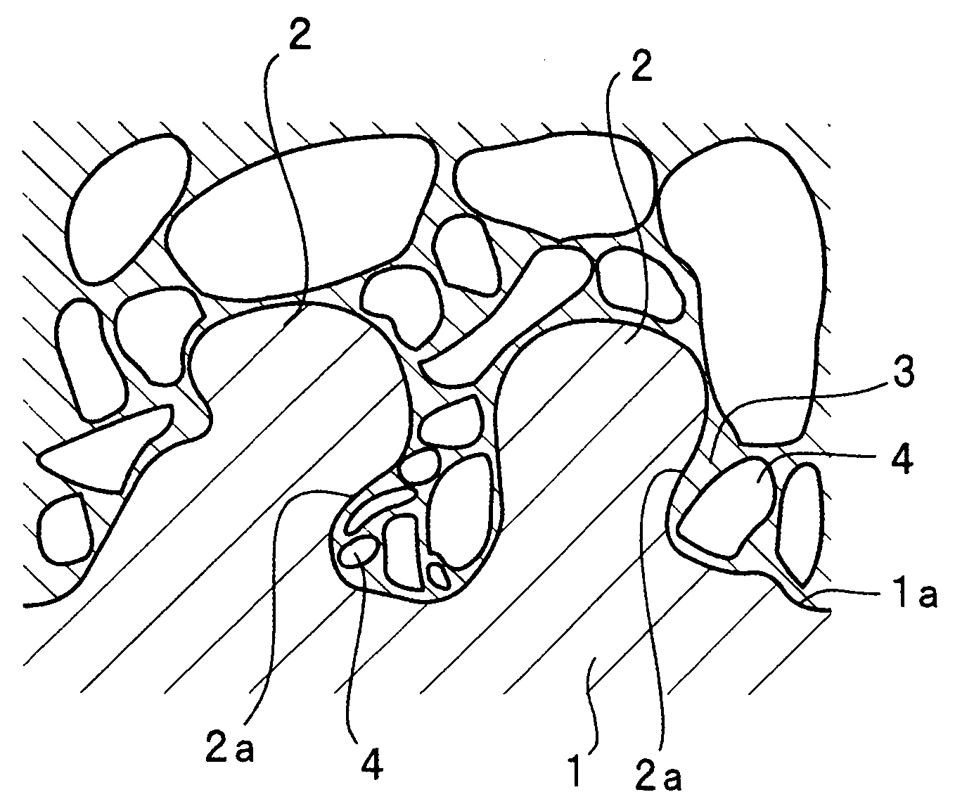
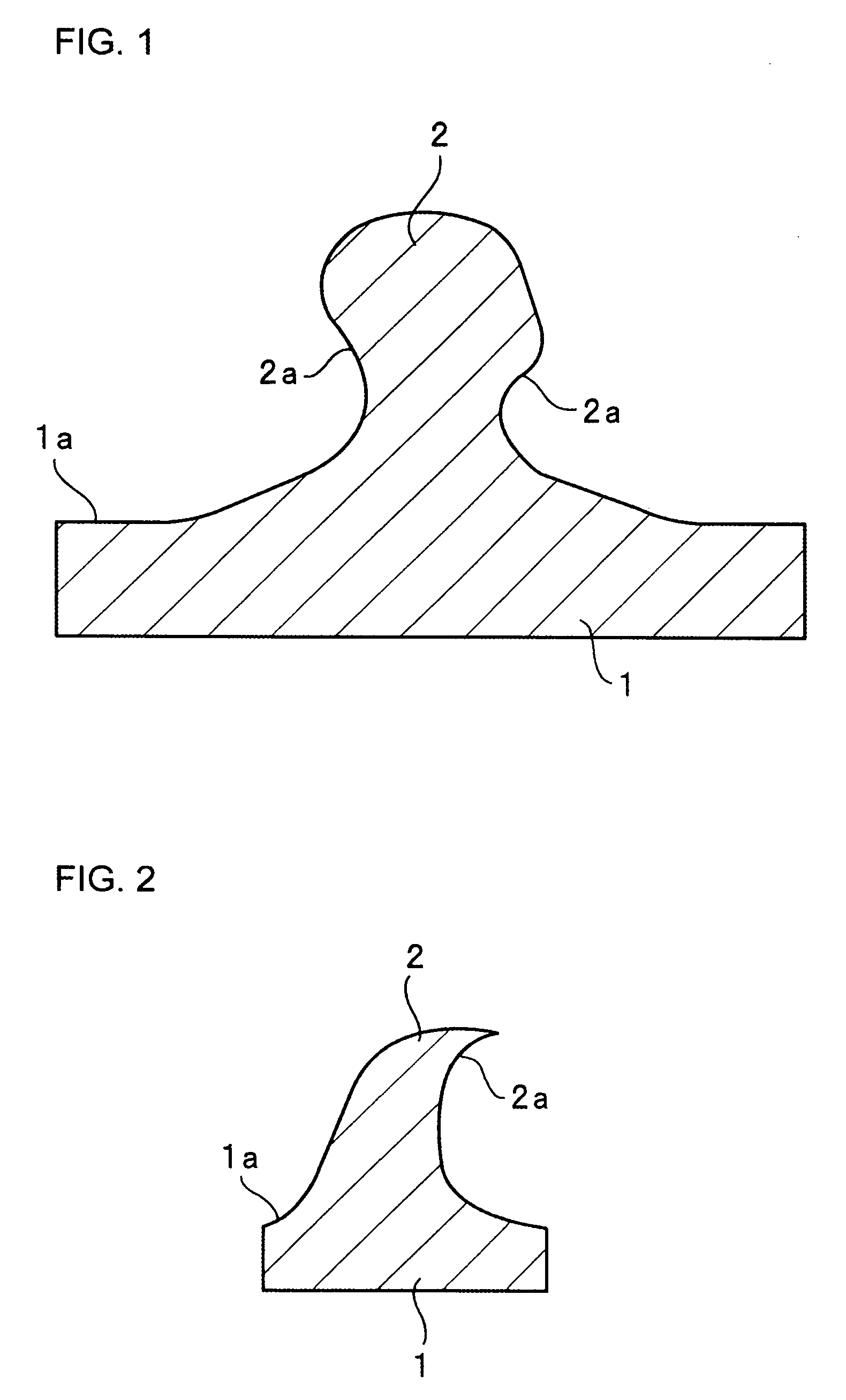
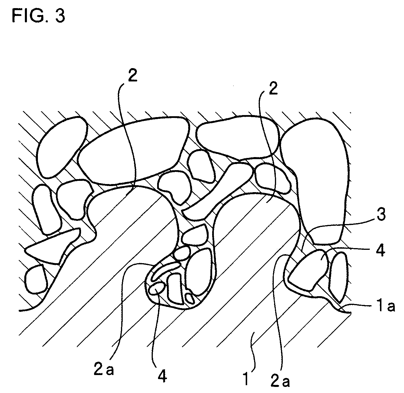
[0075]The current collectors a2, a3 and a4 were fabricated via cover plating, as similar to the current collector a1, and each includes projections having recurved side face portions as shown in FIG. 4, in accordance with the present invention.

[0076]Each battery was evaluated for cycle characteristics in the same...


PUM

PropertyMeasurementUnit
surface roughness Raaaaaaaaaaa
surface roughnessaaaaaaaaaa
thicknessaaaaaaaaaa

Abstract

A negative electrode for a rechargeable lithium battery which is obtained by sintering under a non-oxidizing atmosphere, in the form of a layer on a surface of a metal foil current collector, an anode mix containing a binder and particles of active material containing silicon and / or a silicon alloy; the negative electrode being characterized in that the metal foil current corrector has projections and recesses on its surface, the projection is shaped to have a recurved side face portion that curves more outwardly as it extends closer to a distal end of the projection, and the binder penetrates into spaces defined by the recurved side face portions.

Description

BACKGROUND OF THE INVENTION[0001]1. Technical Field[0002]The present invention relates to a negative electrode for a rechargeable lithium battery, a method for fabrication thereof and a rechargeable lithium battery using the same.[0003]2. Description of Related Art[0004]As one of new types of rechargeable batteries having high power and high energy density, rechargeable lithium batteries have been recently utilized which are charged and discharged by the transfer of lithium ions through a nonaqueous electrolyte solution between the positive and negative electrodes.[0005]The use of lithium-alloying materials, such as silicon materials, as a negative active material of such a rechargeable lithium battery has been studied. Silicon materials and other lithium-alloying materials however expand and shrink in volume when they store and release lithium. Accordingly, such active materials are pulverized or caused to fall off from the current collector upon charge-discharge cycling. This redu...

Claims


Application Information

Patent Timeline
Patent Type & Authority Patents(United States)
IPC IPC(8): H01M4/70H01M4/64H01M4/72B05D5/12H01M4/1395H01M4/36H01M4/38H01M4/62H01M4/66H01M10/05
CPCH01M4/02H01M4/0471H01M4/38H01M4/661H01M4/70H01M4/622Y02E60/122H01M10/052H01M4/386Y02E60/10G01N29/24H05K9/0007
Inventor FUKUI, ATSUSHITORIMAE, MARIKOKUSUMOTO, YASUYUKITARUI, HISAKI
Owner SANYO ELECTRIC CO LTD
Why Eureka
Try Eureka