
Method and apparatus for stand-off chemical detection

a stand-off chemical and detection method technology, applied in the field of stand-off chemical detection methods and equipment, can solve the problems of unsuitable methods for field use to identify unknown and potentially hazardous materials, sampling and analysis poses a real risk to the personnel involved, and pollutes the environment and is toxic to land or water

Inactive Publication Date: 2007-11-20
THE SEC OF STATE FOR DEFENCE IN HER BRITANNIC MAJESTYS GOVERNMENT OF THE UK OF GREAT BRITAIN & NORTHERN IRELAND
View PDF16 Cites 128 Cited by
  • Summary
  • Abstract
  • Description
  • Claims
  • Application Information

AI Technical Summary

Benefits of technology

[0025]As used herein the term stand-off shall be taken to mean that neither an operator nor any element of instrumentation is co-located with a sample. As such when an apparatus is stand-off there is no risk of sample contamination to either personnel or equipment.
[0057]In designing a kit or apparatus for use with the method of the present invention, and for use in the field, it is important to bear in mind the following: making the apparatus as simple to use as possible such that it can be operated by personnel with little or no scientific training; minimising the size and weight of the equipment such that it can be easily transported; maximising the durability of the equipment for different situations, including different temperatures, and minimising the power requirement of the apparatus.

Problems solved by technology

Many materials and substances are deposited on land or water for a variety of different reasons and if they are unwanted and / or dangerous they become contaminants, pollutants and toxic to the land or water.
Although this can successfully identify a wide variety of contaminants including materials with low volatility, the methods are unsuitable for use in the field to identify unknown and potentially hazardous materials.
This is because the sampling and analysis poses a real risk to the personnel involved and because the methods are too slow for effective use during conflict.
However, problems remain, including that without a detailed knowledge of the contaminant it can be difficult to assess the most appropriate clothing, during conflict it is impractical for front line troops to carry large amounts of protective gear and during collection the clothing itself is cross contaminated through exposure.
However, the use of such a vehicle still has several associated problems including contamination of the vehicle during use, exposure of the personnel operating the vehicle either when they enter the contaminated area or conduct the analysis, cost of the vehicle and transportation of the vehicle to the front line.
Although such disclosures provide an advance in sample detection several problems remain.
These include that because such apparatus utilise a mass spectrometer, the sample and the detection means must be co-located and is therefore not suitable for stand off detection.
Despite these developments several limitations remain.
These include that some of the known methods are only useful for detection of gaseous materials; the methods often require tuning the instrumentation to a known wavelength to positively confirm the presence of a single component at once; many of the methods require complex optical and filtering means to deflect the radiation; and that some of the methods rely on heating of a background material which may not be practical in the field.
As previously, although the prior art discloses several improvements in surface analysis there remain several problems when these techniques are considered to solve the present problem.
These include that some of the methods described rely on generating a plasma to interact with the material allowing for subsequent identification using atomic emission or fluorescence spectra which is insufficiently selective to accurately differentiate and identify between a wide range of different materials with low volatility, especially a wide range of organic materials; many of the methods disclosed are operated remotely but are not fully stand-off which results in continued personnel risk and equipment contamination; and, as previously, many of the methods require complex optical and filtering means which might not be practical to position in the field.
However this method is slow because of the requirement to heat the substrate sufficiently to generate a thermal contrast, then acquire and process data and also difficult to use to identify when only a small amount of sample is present.
Again while such an apparatus presents an advance in the field problems still exits.
These include that irradiating the substrate may only provide a weak absorption signal from the contaminant if insufficient energy is transferred from the substrate to the contaminant, heating the substrate sufficiently may require an unduly large amount of energy, and that the contaminant may produce both absorption and emission spectra which lead to a false negative result.

Method used


Image

  • Method and apparatus for stand-off chemical detection
  • Method and apparatus for stand-off chemical detection

Examples


example 1

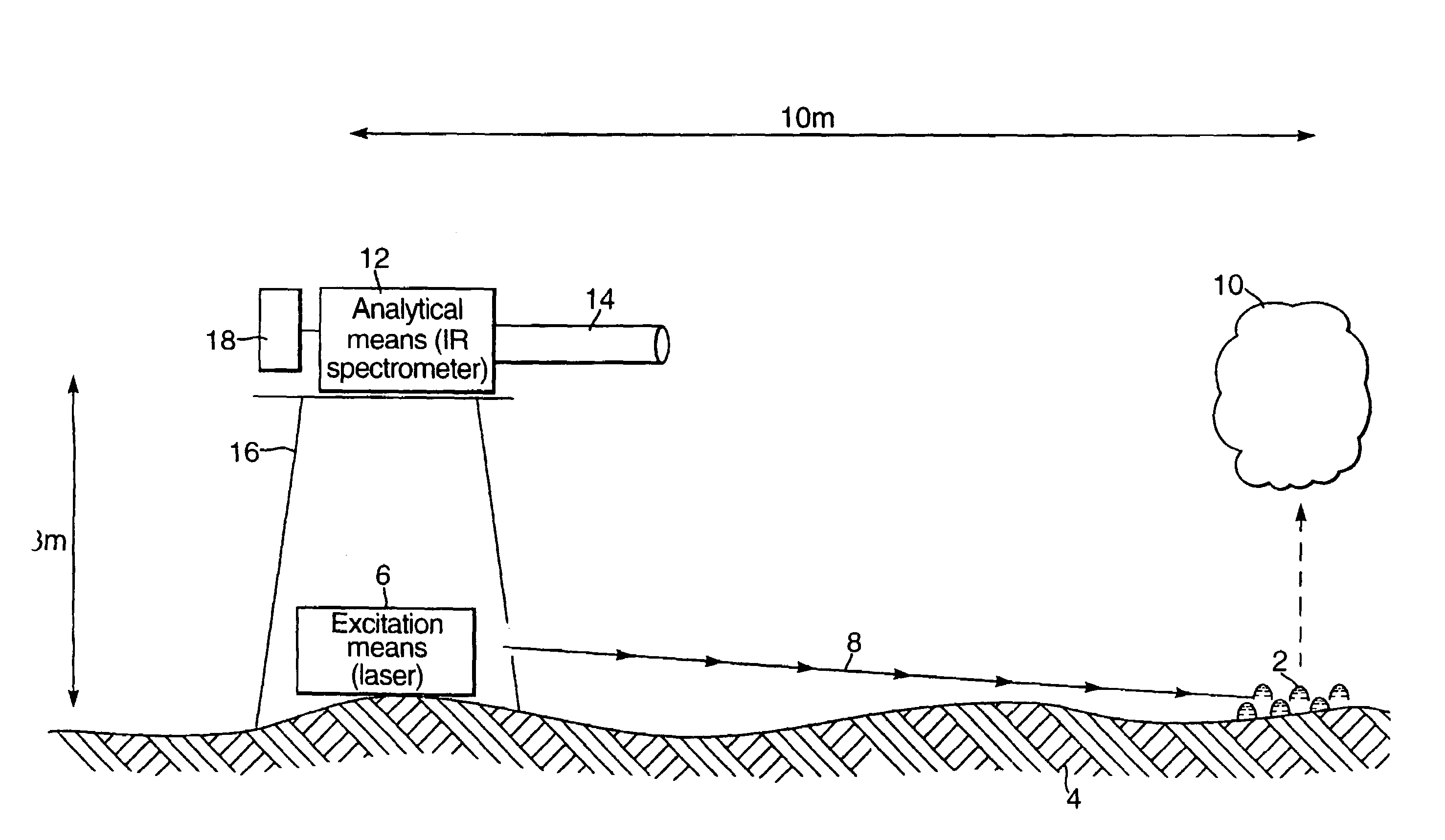
[0062]A continuous wave CO2 laser (Edinburgh Instruments), operating at 9.6 μm, with an output power of 4.5 W, was situated approximately 1 m away from a droplet of liquid methyl salicylate of approximate diameter 10 mm. The laser beam was directed using appropriate mirrors and focussed on to the droplet using a lens made of zinc selenide and then used to vaporise the sample to create a vapour plume directly above the droplet. The infrared emission spectrum of the vapour plume was then measured using a MEDAC AM Fourier Transform Infrared (FTIR) spectrometer, with 1 m focal length collection lens placed in front of the open emission port, situated 1 m away from the vapour and positioned at right angles to the laser. The infrared spectrum was obtained by operating the FTIR at between 1 and 20 scans per second and using a suitable resolution of 1 to 32 cm−1. The collected spectra were compared with library spectra to provide positive identification of the liquid methyl salicylate from ...

example 2

[0063]A continuous wave CO2 laser (Edinburgh Instruments), operating at 9.25 μm, with an output power of 10 W, was situated approximately 5 m away from a droplet of liquid chemical warfare agent of approximate diameter 10 mm. The laser beam was directed unfocussed on to the droplet and then used to vaporise the sample to create a vapour plume directly above the droplet. The infrared emission spectrum of the vapour plume was then measured using a MIDAC AM Fourier Transform Infrared (FTIR) spectrometer, fitted with a Cassegrain telescope with a diameter of 25 cm focused to infinity, situated 5 m away from the vapour and positioned alongside the laser. The infrared spectrum was obtained by operating the FTIR at between 1 and 20 scans per second and using a suitable resolution of 1 to 32 cm−1. The collected spectra were compared with library spectra to provide positive identification of the individual components of the liquid chemical warfare agent mixture.


PUM

PropertyMeasurementUnit
poweraaaaaaaaaa
poweraaaaaaaaaa
diameteraaaaaaaaaa

Abstract

A method, suitable for stand off analysis of a sample (2), comprising: (i) using an excitation means (6) to vaporise the sample (2) thereby producing a vapour plume (10) of molecular species; and (ii) using an analytical means (12) to analyse molecular species within the vapour plume (10) wherein the analytical means (12) analyses the molecular emission spectra of the vapour plume (10). The invention also relates to a kit and an apparatus for use with the same.

Description

CROSS REFERENCE TO RELATED APPLICATIONS[0001]This application is the U.S. national phase of International Application No. PCT / GB2003 / 003440 filed on Aug. 6, 2003 and published in English on Mar. 4, 2004 as International Publication No. WO 2004 / 019020 A1, which application claims priority to Great Britain Application No. 0219541.0 filed on Aug. 22, 2002, the contents of which are incorporated by reference herein.[0002]This invention relates to a method for detection and identification of one or more chemical species. More particularly this invention relates to a method for the stand-off vaporisation and identification of one or more materials with low volatility. This invention also relates to an apparatus and kit for implementing the method.[0003]Many materials and substances are deposited on land or water for a variety of different reasons and if they are unwanted and / or dangerous they become contaminants, pollutants and toxic to the land or water. To effectively remediate the area...

Claims


Application Information

Patent Timeline
Patent Type & Authority Patents(United States)
IPC IPC(8): G01J3/30G01N21/71
CPCG01N21/718G01N2021/3595G01N2021/1793
Inventor GANDHI, SUNILKUMAR BABULALJEFFERY, PAUL DOUGLASMCANALLY, GERARD DAVID
Owner THE SEC OF STATE FOR DEFENCE IN HER BRITANNIC MAJESTYS GOVERNMENT OF THE UK OF GREAT BRITAIN & NORTHERN IRELAND
Learn More