Wavelength monitoring apparatus

a technology of wavelength monitoring and monitoring apparatus, which is applied in the direction of optical radiation measurement, instruments, semiconductor lasers, etc., can solve the problems of difficulty in assembling inability to carry out temperature compensation in a wide temperature range, and prior art wavelength monitoring devices cannot carry out temperature compensation in a range of operating temperatures of semiconductor lasers

Inactive Publication Date: 2007-11-27
MITSUBISHI ELECTRIC CORP
View PDF14 Cites 7 Cited by
  • Summary
  • Abstract
  • Description
  • Claims
  • Application Information

AI Technical Summary

Benefits of technology

[0136]As a result, the wavelength monitoring device whose wavelength discriminating characte...

Problems solved by technology

However, a problem with the prior art wavelength monitoring device constructed as mentioned above is that the two uniaxial birefringent crystals have to be accurately positioned with respect to each other and the optical axis of the incident optical signal, and it is therefore difficult to assemble the prior art wavelength monitoring device.
In the prior art wavelength monitoring device, though the adjustment of the length of each uniaxial birefringent crystal in the direction of the optical axis of the incident optical signal can implement temperature compensation, the temperature compensation cannot be carried out in a w...

Method used


Image

  • Wavelength monitoring apparatus
  • Wavelength monitoring apparatus
  • Wavelength monitoring apparatus

Examples


embodiment 1

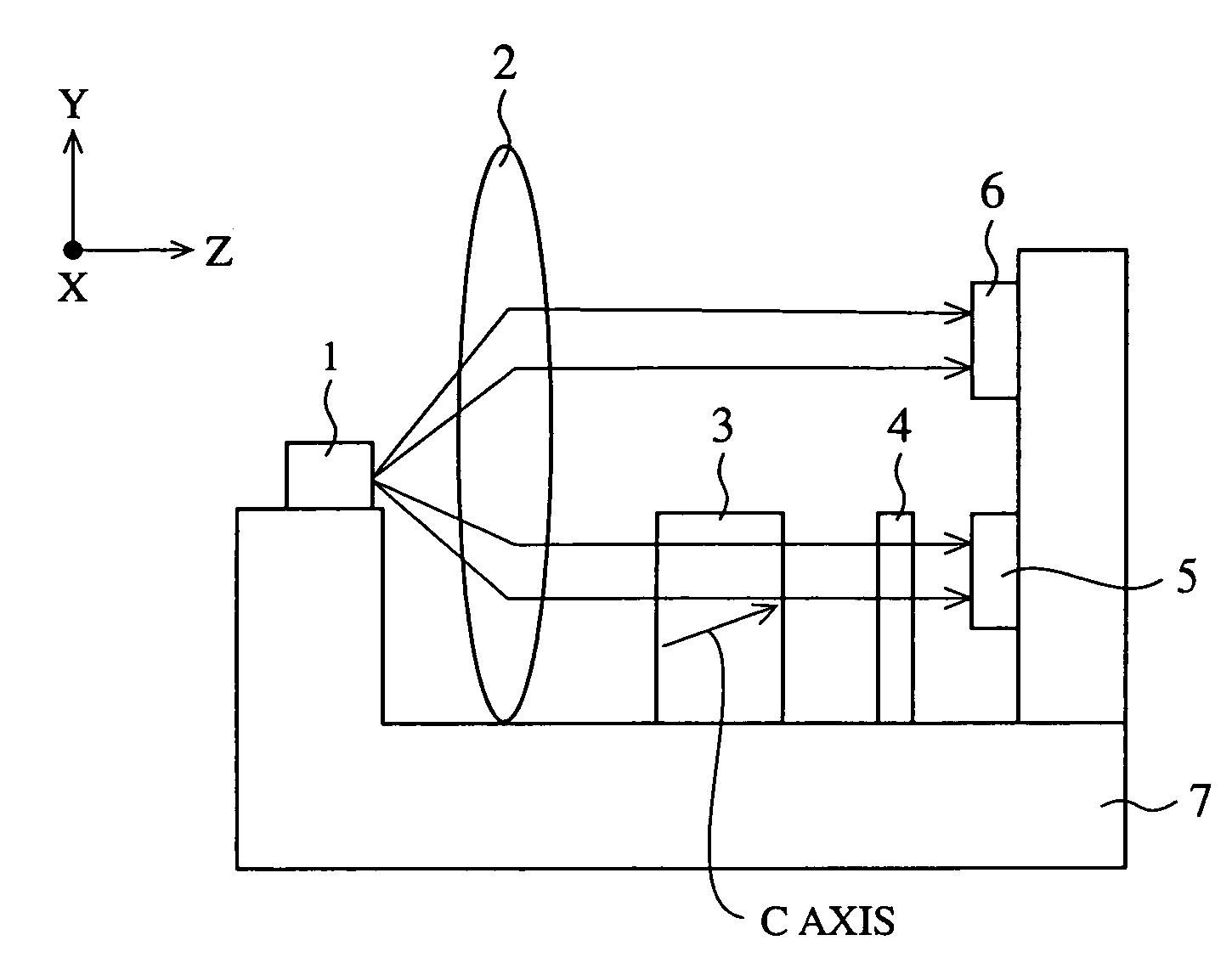
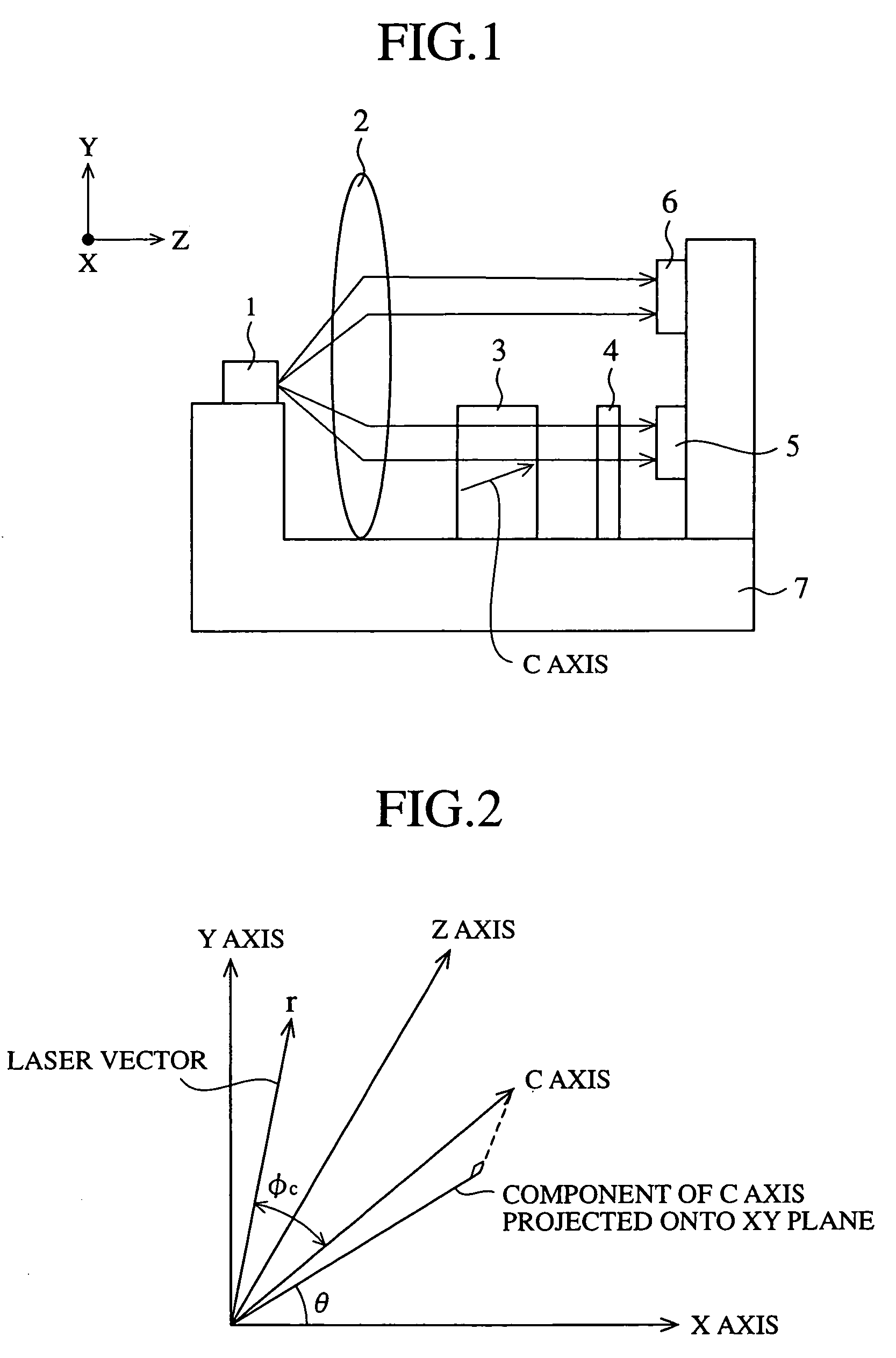
[0177]FIG. 1 is a block diagram showing a wavelength monitoring device in accordance with embodiment 1 of the present invention.

[0178]In FIG. 1, reference numeral 1 denotes a semiconductor laser for emitting laser light (referred to as an optical signal from here on) that is polarized in a direction. For example, the semiconductor laser 1 can be a distributed feedback (DFB) laser having a grating in an active layer, a tunable laser diode that can change the wavelength of laser light emitted out thereof according to an electric current supplied thereto or temperature, or a composite-type laser (EA / LD) in which an electroabsorption element and a laser diode are disposed in series. Reference numeral 2 denotes a lens for converging and collimating the optical signal emitted from the semiconductor laser 1 so as to output the optical signal as parallel light. A line that connects the center of an emitting face of the semiconductor laser 1 and the center of the lens 2 is a laser optical ax...

embodiment 2

[0237]In embodiment 1, a uniaxial birefringent crystal is so determined and placed in the wavelength monitoring device as to meet the temperature compensation condition given by the equation (13). However, when the change dΔn(φc) / dT in the refractive index difference with respect to the temperature of the uniaxial birefringent crystal and / or the linear expansion coefficient α in the equation (13) change dependently upon the temperature of the uniaxial birefringent crystal, there is a possibility that the temperature compensation condition is satisfied at a certain standard temperature, whereas the temperature compensation condition is not satisfied at other temperatures. To solve this problem, in accordance with this embodiment, a temperature compensation condition that temperature compensation is surely implemented for the uniaxial birefringent crystal in a wide temperature range in which a semiconductor laser 1 can operate is newly found, and the temperature compensation condition...

embodiment 3

[0267]In accordance with this embodiment, there is provided a wavelength monitoring device that can adjust the wavelength discriminating characteristics of a uniaxial birefringent crystal and a polarizer according to a desired reference wavelength.

[0268]FIG. 25 is a block diagram showing the wavelength monitoring device in accordance with embodiment 3 of the present invention. The wavelength monitoring device in accordance with embodiment 3 of the present invention has the same components as those of the wavelength monitoring devices of embodiments 1 and / or 2 which are designated by the same reference numerals, and the explanation of those components will be omitted hereafter.

[0269]Reference numeral 31 denotes a uniaxial birefringent crystal. This uniaxial birefringent crystal has a crystal cut-out surface for receiving an optical signal, the cut-out surface being parallel to an xy plane, and has a C axis oriented in a direction determined by inclining a vector on a y axis in the xy...


PUM


Abstract

An optical signal emitted from a semiconductor laser is converged by a lens and then received by a single uniaxial birefringent crystal having a C axis that is inclined at an angle other than 90 degrees against a laser optical axis to output an optical signal having a polarized wave component of constant intensity corresponding to the wavelength of the optical signal regardless of temperature changes. The optical signal has an ordinary ray vibrating in a direction perpendicular to a plane including both the C axis and the laser optical axis, and an extraordinary ray vibrating in a direction perpendicular to both the ordinary ray and the laser optical axis. A first main photo detector detects the intensity of a p-polarized component of the optical signal that has passed through a polarizer and a second photo detector directly receives the optical signal converged by the lens.

Description

[0001]This application is the national phase under 35 U.S.C. § 371 of PCT International Application No. PCT / JP01 / 003853 which has an International filing date of May 8, 2001, which designated the United States of America.FIELD OF THE INVENTION[0002]The present invention relates to a wavelength monitoring device that is used for optical fiber communications and that discriminates and monitors the wavelength of an optical signal emitted from a semiconductor laser by using a uniaxial birefringent crystal.BACKGROUND OF THE INVENTION[0003]Dense wavelength division multiplexing (DWDM) optical communications have been used for optical communication systems using optical fibers. In DWDM optical communications, in order to multiplex light rays emitted from various semiconductor lasers it is necessary to stabilize the wavelengths of those light rays with a high degree of accuracy. Therefore, a wavelength monitoring device that discriminates and monitors the wavelength of a light ray emitted f...

Claims


Application Information

Patent Timeline
IPC IPC(8): H01S3/13G01J4/04G01J9/00H01S5/022H01S5/0687
CPCG01J4/04H01S5/0687G01J9/00H01S5/02252H01S5/02326
Inventor IMAKI, MASAOHIRANO, YOSHIHITOSATOU, MAKOTOMASUDA, KENJIADACHI, AKIHIROTAKAGI, SHINICHINISHIMURA, YASUNORI
Owner MITSUBISHI ELECTRIC CORP
Why Eureka
Try Eureka