Apparatus and method of dispensing small-scale powders

a technology of small-scale powder and apparatus, which is applied in the direction of heat inorganic powder coating, hair combs, roads, etc., can solve the problems of high material cost and process risk, complex process equipment, and the most expensive and unreliable part of the sensor and actuator, so as to facilitate the deposition

Inactive Publication Date: 2008-01-08
WISCONSIN ALUMNI RES FOUND
View PDF6 Cites 71 Cited by
  • Summary
  • Abstract
  • Description
  • Claims
  • Application Information

AI Technical Summary

Benefits of technology

[0023]The preferred embodiments of the present invention are directed to a feed mechanism capable of dispensing small-scale fabrication materials such as dry engineering powders and biological cells (e.g., animal cells such as those of a chicken). Such an apparatus can be used in, for example, a laser-assisted micro-SDM process that integrates additive (laser micro-cladding) and subtractive (laser micro-machining) processes to form 3D heterogeneous MEMS. A vibrating device of the feed mechanism (that generates ultrasonic vibration) is used to facilitate the deposition.
[0031]According to a further aspect of the preferred embodiment, a cooling system is coupled to the actuator to improve the flow rate of the particles. Preferably, the actuator is a piezoelectric plate and the cooling system cools the actuator when the actuator is driven by a voltage generally above a threshold voltage.

Problems solved by technology

Classically, sensors and actuators have been the most costly and unreliable part of a macro-scale system which may include some combination of sensors, actuators and electronics.
In general, CVD or chemical vapor deposition techniques (such as low CVD) produce superior films to physical vapor deposition techniques (PVD), but at the expense of higher material cost and higher process risk.
In either case, the process equipment is complicated, expensive and typically requires clean-room conditions.
These MEMS techniques are two-dimensional (2D) processes with multiple steps that require complicated processing procedures, and only a limited number of materials can be processed through the use of these techniques.
And, as 2D processes, these silicon-based techniques are not easily adaptable to building 3D devices such that enclosed volumes of arbitrary shape and composition are difficult to make without the use of micro assembly.
Overall, although the most widely used MEMS fabrication material, there are significant drawbacks associated with fabricating MEMS devices with silicon.
Conventional methods of fabricating silicon-based devices have a litany of limitations including the types of devices that can be produced, as well as strict process conditions.
Nevertheless, little work has been done to successfully attain efficient micro-manufacturing techniques for the fabrication of functionally and geometrically complex heterogeneous MEMS.
A significant challenge to the proliferation of MEMS devices is the development of processes that can be implemented in the wide range of applications and materials.
Although useful for their particular purposes, each of these micro SFF processes are not suitable to build 3D heterogeneous MEMS due to their limited flexibility in changing material composition in situ.
However, SDM processes have not been scaled down to the small-scale, e.g., micro-world.
Nevertheless, known laser micro deposition processes are not capable of in situ local composition control of the material being deposited.
The primary drawback with known systems is the inability to mix and deliver various submicron / nano dry powders without additional chemical mixtures.

Method used


Image

  • Apparatus and method of dispensing small-scale powders
  • Apparatus and method of dispensing small-scale powders
  • Apparatus and method of dispensing small-scale powders

Examples


Embodiment Construction

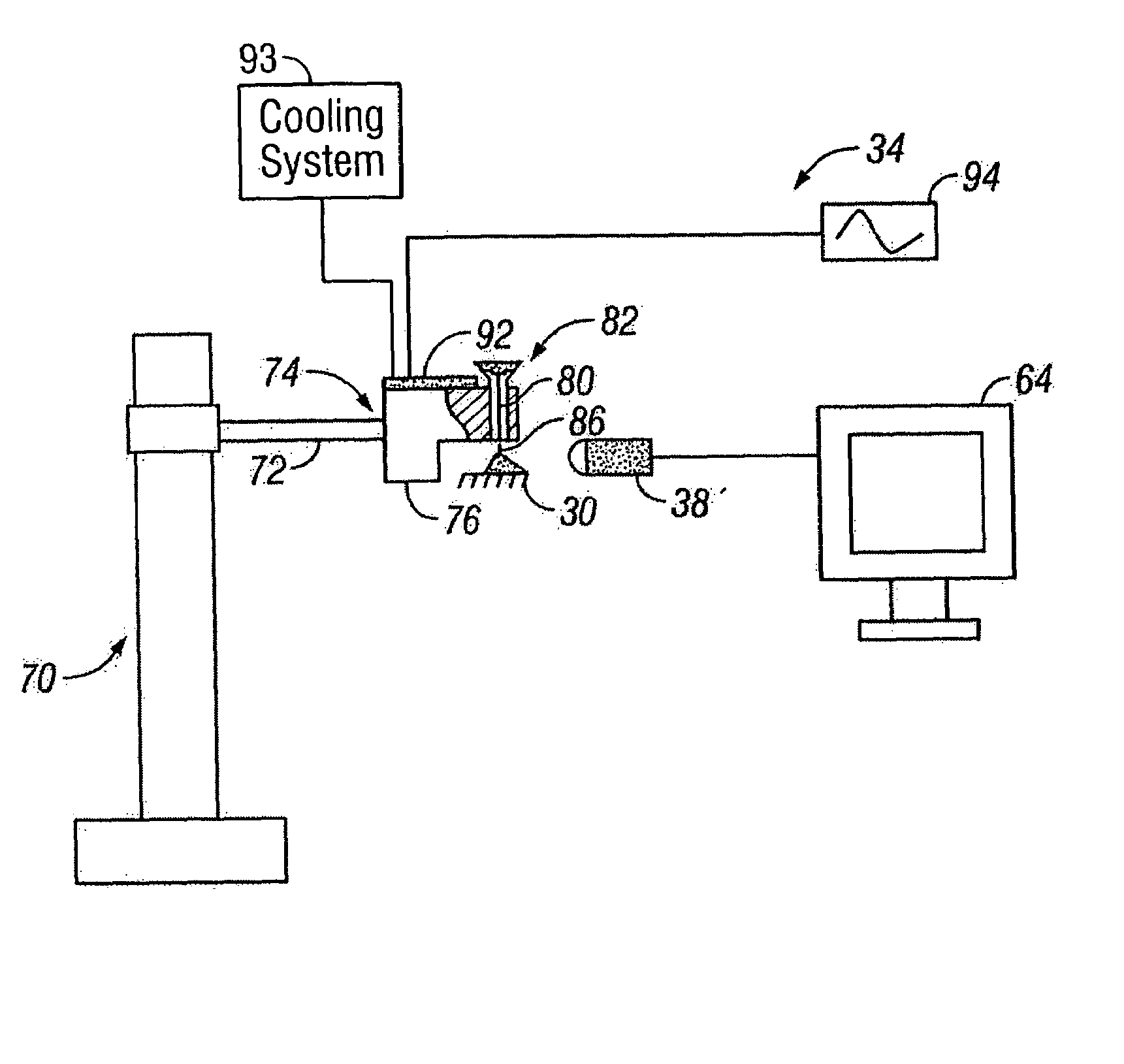
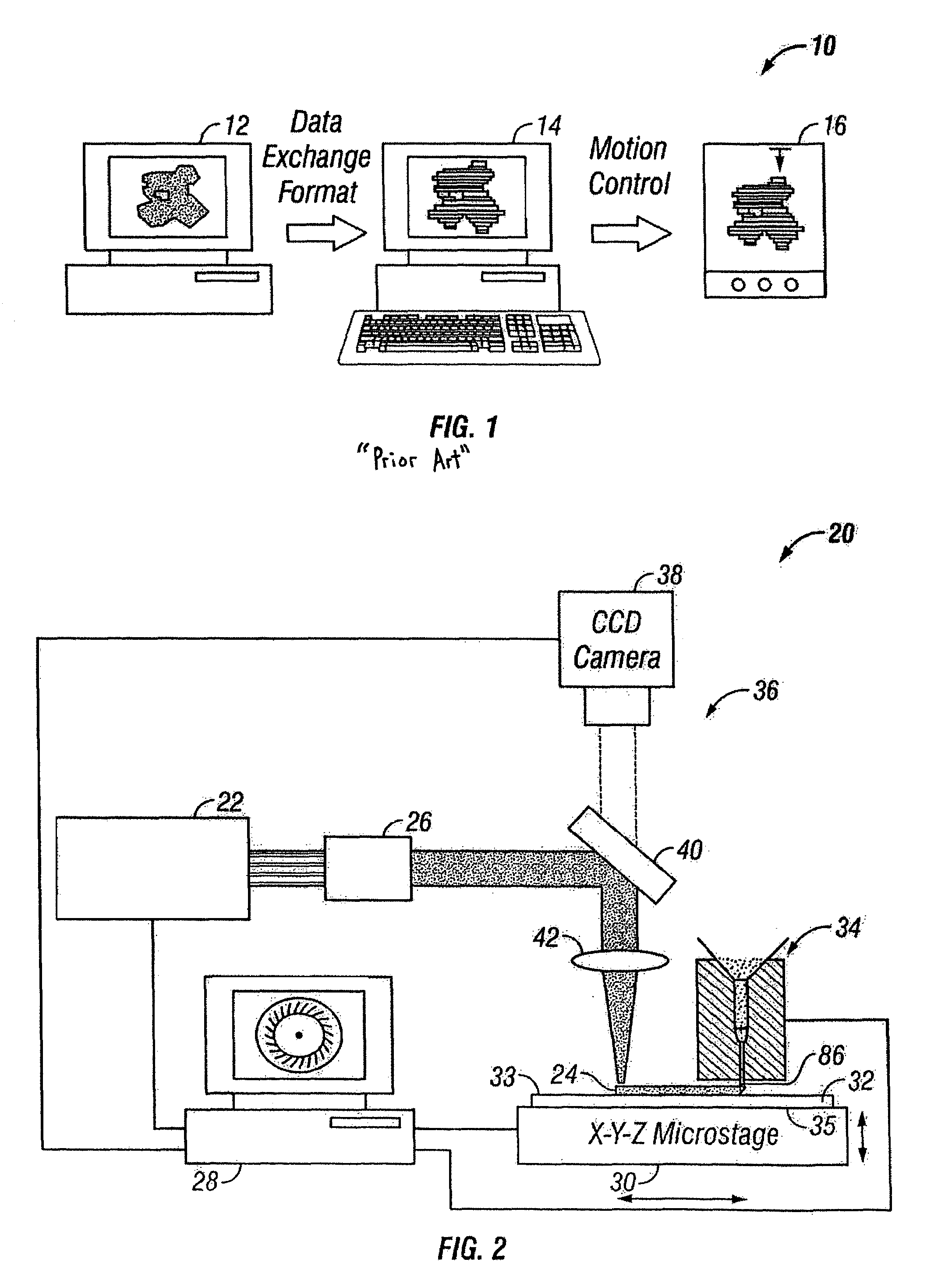
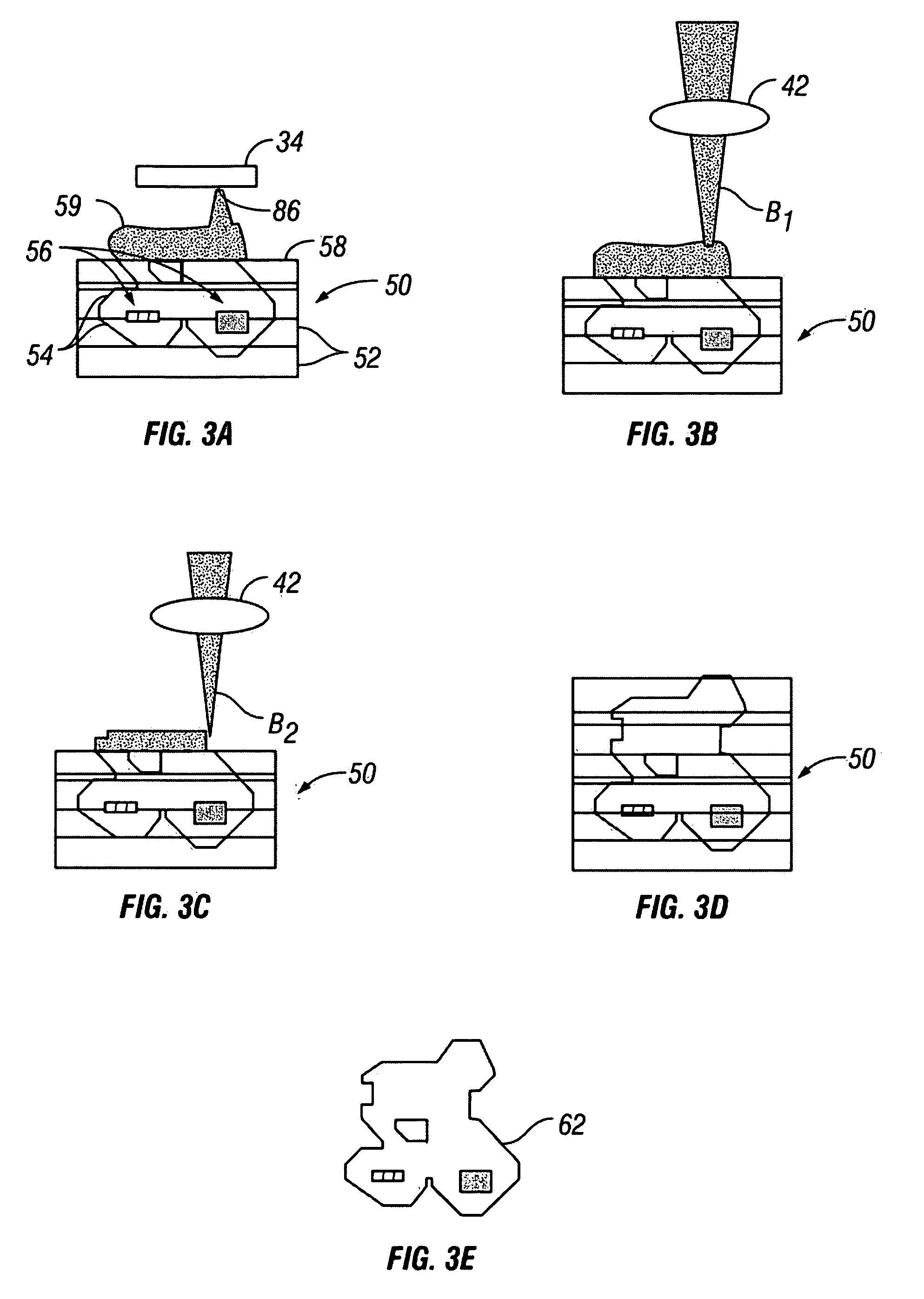
[0058]Turning initially to FIG. 2, a small-scale manufacturing system 20 for producing, for example, MEMS devices is shown. Manufacturing system 20 is based on laser-assisted SDM and includes a laser source 22 capable of micro-deposition and micro machining of various materials disposed on the substrate 32. Laser 22 is preferably a Nd:YAG (Neodymium: Yttrium Aluminum Garnet) laser for the material processing. To realize the additive and subtractive processes at small scale (e.g., micro scale) laser 22 is pulsed with different harmonic modes including 1064 nm, 532 mm, 355 nm, and 266 mm to provide the micro deposition and micro machining, as described below. Overall, laser source 22 operates as a micro additive and subtractive tool in a small scale SDM system. The output energy level of laser 22 is approximately 1.95 J / pulse at 1064 mm, 0.95 J / pulse at 532 nm, 0.4 J / pulse 355 mm, and 0.175 J / pulse for 266 mm.

[0059]With further reference to FIG. 2, a laser beam attenuator 26 is used t...


PUM

PropertyMeasurementUnit
gap distanceaaaaaaaaaa
velocityaaaaaaaaaa

Abstract

An apparatus and method of dispensing small-scale powders for a variety of applications, including, for example, fabricating a three-dimensional heterogeneous small-scale device, includes using a feed mechanism that causes motion of the powder particles and the steps of depositing fine heterogeneous materials (such as dry powders and biological materials) towards a substrate. The depositing step preferably includes providing a feed mechanism having an input to receive the material, an output, and a source of ultrasonic vibration to impart a torsional force on the material so as to precisely discharge the material from the output. To improve particle flowability, a cooling system is provided to cool the source, generally above a threshold input voltage.

Description

CROSS-REFERENCE TO RELATED APPLICATIONS[0001]This application is a continuation-in-part of U.S. Ser. No. 10 / 192,228, filed Jul. 10, 2002, now abandoned which claims the benefit of U.S. Provisional Application Ser. No. 60 / 375,277, filed Apr. 24, 2002, the entire contents of each being hereby expressly incorporated by reference herein.BACKGROUND OF THE INVENTION[0002]1. Field of the Invention[0003]The present invention is directed to an apparatus and method of depositing small-scale powders, and more particularly dispensing powders for a variety of applications including manufacturing small-scale devices such as micro-electromechanical systems (MEMS), biomedical instruments and display instruments.[0004]2. Description of Related Art[0005]Micro-electromechanical systems (MEMS) technology is a manufacturing technology that embodies a way of making complex electromechanical systems using batch fabrication techniques similar to the way integrated circuits are made, and making such electro...

Claims


Application Information

Patent Timeline
Patent Type & Authority Patents(United States)
IPC IPC(8): B05C19/00B05B3/14B05B7/00C23C24/00C23C24/08C23C24/10C23C26/02H05K3/10
CPCC23C24/00C23C24/08C23C24/10C23C26/02H05K3/102H05K2203/0126H05K2203/107H05K2203/1131B33Y30/00B33Y40/00
Inventor LI, XIAOCHUNYANG, YONGCHOI, HONGSEOK
Owner WISCONSIN ALUMNI RES FOUND
Why Eureka
Try Eureka