
Short-range automotive radar transceiver

a transceiver and automotive technology, applied in the field of short-range radars, can solve the problems of low efficiency (about 2%-4%), high cost of assembling and tuning wave-guide diode oscillators, and low phase noise and power output, and achieve low cost of automotive radars, small size and mass of transceivers, and high reproducibility of operating parameters

Inactive Publication Date: 2008-01-29
AUTOMOTIVE TECH INT +1
View PDF18 Cites 12 Cited by
  • Summary
  • Abstract
  • Description
  • Claims
  • Application Information

AI Technical Summary

Benefits of technology

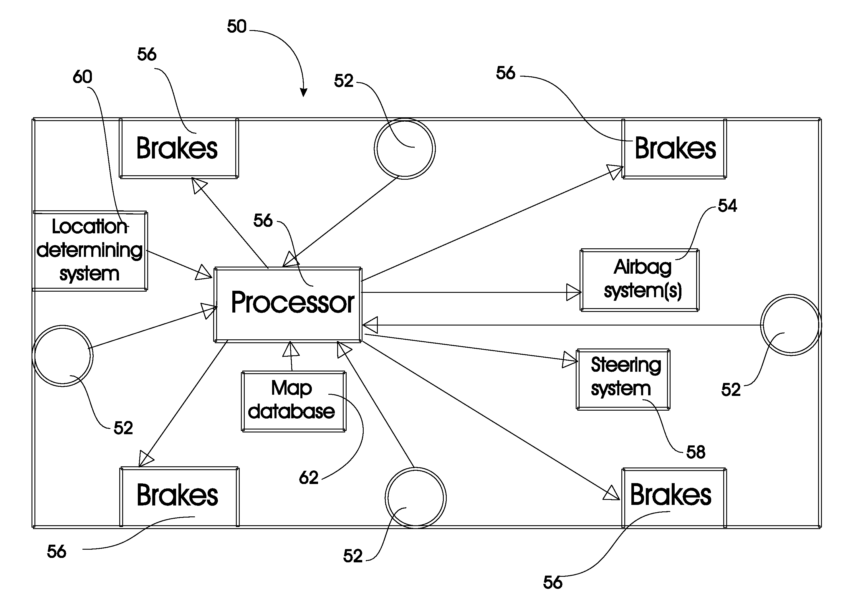
"The present invention provides new and improved short-range automotive radar transceivers that use active IMPATT frequency multipliers with a high multiplication factor to form a highly stable RF signal at any point in the MM-wave range. This efficient and economical way of forming a stable RF signal allows for the use of a single active element in the transmit and receive antennas, reducing the number of active elements required and improving reproducibility of operating parameters. The transceivers provide high transmitting power at low phase noise levels, low noise levels, mechanical strength, reliability, compactness, and the ability for large-scale production and low cost. The invention also includes a vehicle with the radar transceivers and a processor for controlling components based on the output from the transceivers."

Problems solved by technology

The most significant requirements for it are the levels of phase noise and power output.
It should be noted that, although the GD oscillators can provide the required power output and have quite satisfactory noise characteristics, the cost of assembling and tuning wave-guide diode oscillators is very high.
In addition, their efficiency is low (about 2%-4%), while the volume physical structure of diodes hampers realization of transceiver construction as a planar structure.
However, the specifications of the present-day MICs operating in the 76-77 GHz frequency range still do not meet the imposed requirements.
The problems of integration and packaging of active devices, as well as their mechanical and electric coupling with each other and the rest of transceiver components, still remain largely unsolved and potentially expensive.
In particular, the problem of highly linear frequency tuning is transferred into the microwave range where standard, available and reliable transistor VCOs are used.
Realization of EMR sources with reasonable values of this parameter (especially in the short-wave region of the MM-wave range) creates a difficult problem.
However, the number of active devices (and, as a result, the cost of the whole system) grows considerably.

Method used


Image

  • Short-range automotive radar transceiver
  • Short-range automotive radar transceiver
  • Short-range automotive radar transceiver

Examples


Embodiment Construction

1. Hybrid Integrated Waveguide Transceiver of Automotive Radar with Two Antennas

1.1 General Description of the Operation of Radar Transceiver with Two Antennas

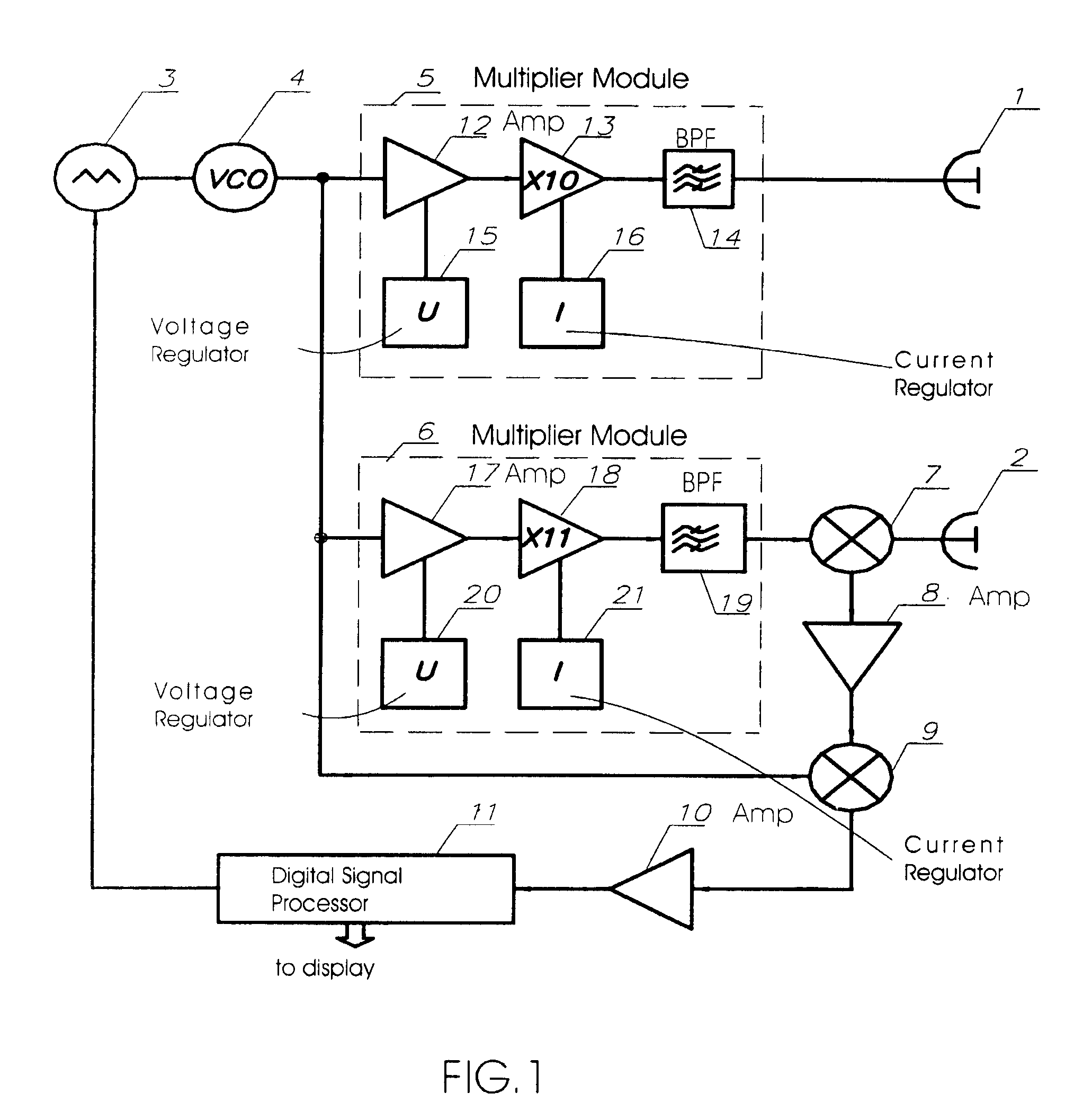
[0045]Referring first to FIG. 1, a block diagram of a transceiver operating in the 76-77 GHz frequency range in accordance with the invention is shown. One intended use of this transceiver is as a front-end of short-range FMCW automotive radar. The circuit of this transceiver involves two separate antennas—transmit antenna 1 and receive antenna 2. Use of two separate antennas, which should be adequately isolated from each other, enables a considerable increase in transceiver potential and excludes application of MM-wave isolators. The active MM-wave components of this transceiver operating at 76-77 GHz are highly efficient frequency multiplier modules with high multiplication factor implemented on silicon IMPATT diodes. The main principles of construction of this frequency multiplier over the whole MM-wave range (30-300 GHz) a...


PUM


Abstract

Automotive vehicle including a radar transceiver each including a heterodyne active IMPATT multiplier module arranged to receive a signal from a VCO, a first balance mixer arranged to receive a signal from a VCO, a second balance mixer arranged to receive a signal from a receive antenna and the IMPATT multiplier module and derive a first intermediate frequency signal, a first amplifier for amplifying the output of the second balance mixer and providing the amplifier output to the first balance mixer, and a second amplifier for amplifying the output of the first balance mixer. The vehicle also includes a processor which receives output from the second amplifier of each transceiver and generates a control signal for controlling one or more vehicular components based on the output from the second amplifier(s). The components can be part of a collision avoidance system, blind spot monitoring system and the like.

Description

CROSS REFERENCE TO RELATED APPLICATION[0001]This application claims priority under 35 U.S.C. §119(e) of U.S. provisional patent application Ser. No. 60 / 636,574 filed Dec. 16, 2004, which is incorporated by reference herein.BACKGROUND OF THE INVENTION[0002]1. Field of the Invention[0003]This invention relates in general to short-range radars, and in particular, to transceivers of automotive radars of the Precise Positioning System (PPS) which is intended to be a constituent of the Intelligent Vehicle Initiative (IVI) of the U.S. government. Once realized, this system will provide a determination of a safe and precise location of a vehicle in a traffic lane on the road, prevent traffic accidents when the vehicle is exiting the roadway and otherwise reduce the likelihood of traffic accidents. The automotive radars serve as sensors of the PPS that provide its secure and efficient round-the-clock functioning under any weather conditions.[0004]2. Description of the Prior Art[0005]A crucia...

Claims


Application Information

Patent Timeline
Patent Type & Authority Patents(United States)
IPC IPC(8): G01S13/93G01S7/28G01S13/931
CPCG01S7/032G01S7/35G01S13/343G01S2013/9321G01S2013/9332G01S2013/9342G01S2013/9346G01S13/931G01S2013/9318G01S2013/93185G01S2013/9315
Inventor BOLTOVETS, NIKOLAI S.BASANETS, VLADIMIR V.ZORENKO, ALEKSANDER V.MALTSEV, SERGEI B.ODNOLKO, ANATOLIY F.RUDYK, VASILII I.SOBOLEV, DMITRII V.SHEVCHUK, SERGUEI D.MARKOV, ALEXANDER S.MALTSEVA, IRYNA A.PAVLYUCHENKO, ANDREI V.RUKIN, VLADIMIR P.MAKOVENKO, SERGEI V.BREED, DAVID S.
Owner AUTOMOTIVE TECH INT
Learn More