Inexpensive variable rep-rate source for high-energy, ultrafast lasers

a laser and ultra-fast technology, applied in semiconductor lasers, active medium materials, instruments, etc., can solve the problems of niobate modulators, degraded signals, and increased telecommunication systems frequency, and achieve cost-effectiveness, lower repetition rates, and high pulse energy

Inactive Publication Date: 2008-02-12
IMRA AMERICA
View PDF21 Cites 37 Cited by
  • Summary
  • Abstract
  • Description
  • Claims
  • Application Information

AI Technical Summary

Benefits of technology

[0013]One object of this invention is to convert relatively long pulses from rep-rate variable ultrafast optical sources to shorter, high-energy pulses suitable for sources in high-energy ultrafast lasers. Another object of this invention is to take advantage of the need for higher pulse energies at lower repetition rates so that such sources can be cost effective.

Problems solved by technology

There are many technical challenges in increasing the frequency of telecommunication systems.
The laser diode can be directly modulated, however, direct modulation of the diode typically imposes a spectral chirp on the laser diode output that degrades the signal after propagation some distance down a fiber.
It is not certain that lithium niobate modulators and the related electronics will be able to reach the frequencies and picosecond and subpicosecond pulse widths needed for the systems of the future.
A disadvantage with the present telecom gain-switched diode designs is due to the low pulse energies required and generated.
Under these conditions, the nonlinearity for fiber pulse compression is small and so the fibers are usually quite long and expensive, particularly if the fiber is dispersion decreasing fiber.
In addition, a nonlinear optical device is also often required to remove a long pulse pedestal after the fiber pulse compressor.
1268-70 (2002)) This three element compressor in addition to the diode makes these systems expensive.
Femtosecond mode-locked fiber lasers do not normally have sufficient pulse energies and the pulses are often longer than desired for these nontelecom sources.
A compression factor of 100 can be obtained by this method but typically a smaller factor is used since pulse energy and length becomes too sensitive.
It does not teach parabolic pulse amplification or pulse compression for the pulses from gain switched laser diodes or microchip lasers that are the initial sources for the rather long pulses.

Method used


Image

  • Inexpensive variable rep-rate source for high-energy, ultrafast lasers
  • Inexpensive variable rep-rate source for high-energy, ultrafast lasers
  • Inexpensive variable rep-rate source for high-energy, ultrafast lasers

Examples


first embodiment

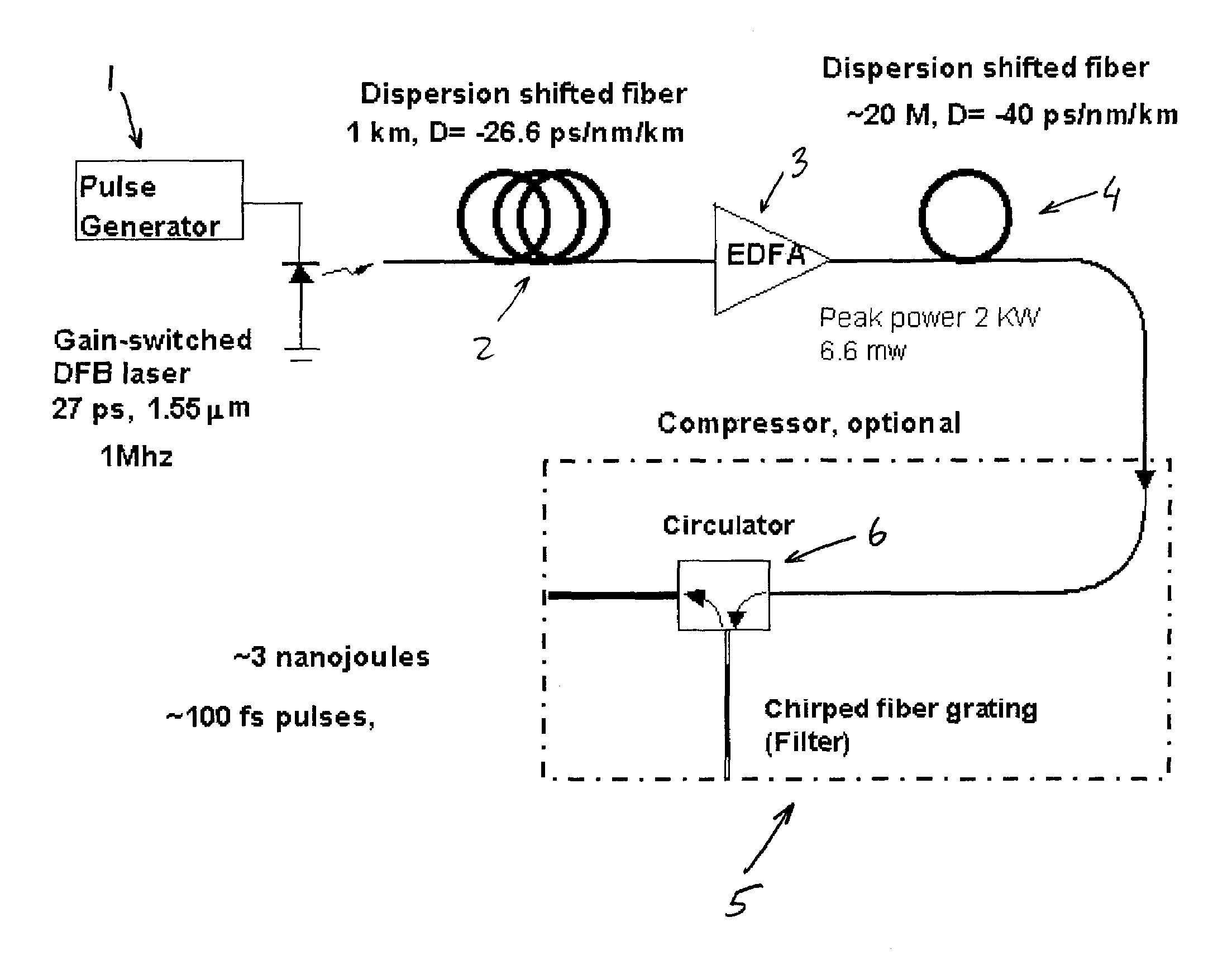
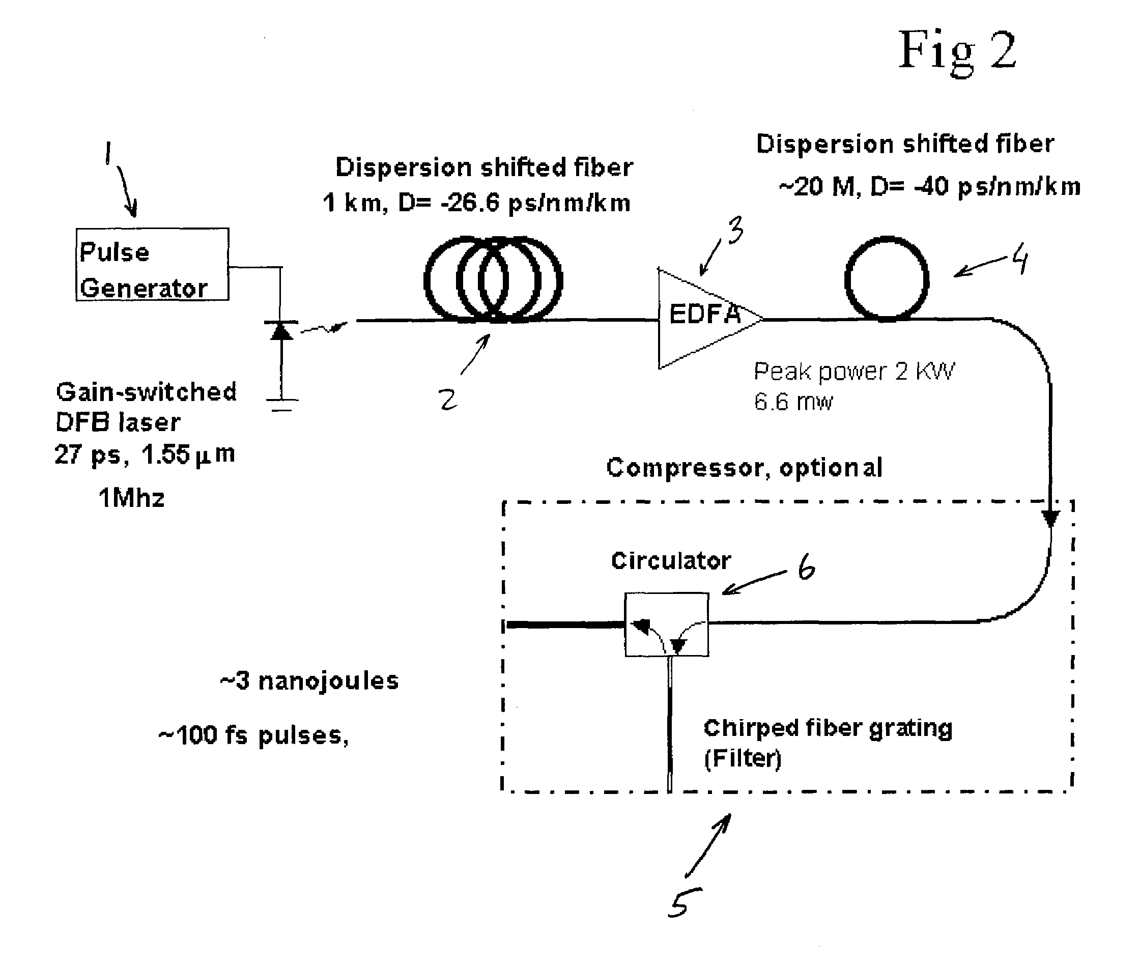
[0034]In the first embodiment shown in FIG. 2, a gain switched laser diode as is described in Ahmed et al is used as the source 1. The chirped 27 picosecond pulse from DFB laser diode at 1550 nm is recompressed to about 3.3 ps in a dispersion shifted fiber 2. This is about 1 km long with D=−26.6 ps / nm / km. The pulse is now about 2× transform limited. The chirp compensation is sufficiently accurate as is described in Mestadagh, D., “Fiber-grating pulse compressor: Performance with initially chirped pulses” Applied Optics 26, pp. 5234-5240 (1987). These pulses are then amplified in an erbium fiber amplifier (EDFA) 3 with a gain of approximately 30 db up to 2 kW peak power. The amplifier is designed so little self-phase modulation takes place in the amplifier. This can be accomplished with a short fiber length (˜10 M) and a large effective area of the mode (˜100 μm2). The rest of the fiber pulse compressor consists of an undoped fiber 4. The primary constraint on this fiber is positive ...

second embodiment

[0040]In the second embodiment as is shown in FIG. 3, the short pulse from the laser diode is generated by a method other than gain switching the laser diode. The technique employed here is an external lithium niobate modulator 32 after a cw laser diode 31. The advantage with this method is that little chirp is imparted on the pulse so that chirp compensation is not necessary. This method is commonly used in the telecommunications field. However, one specification that is more critical for this application than for telecommunications is the extinction ratio. The typical extinction ratio for a lithium niobate modulator is 20-30 db. This specification can be found from the data sheet for JDSU model no. 21013142. If this modulator is turned on to give a 100 ps pulse at a 10 kHz pulse rate, then the pulse is on for 100 ps while the cw is on for 0.1 ms. This means that the cw component is on the order of 105 longer than the pulse. If the cw amplitude is cut by just 30 db, the average pow...

third embodiment

[0042]Another configuration for a two-stage compressor is shown in the third embodiment in FIG. 4. It utilizes a four-port circulator 45 with an additional fiber grating 47. The second fiber compressor is spliced in front of the first fiber grating. The first pass through the extra 40 cm of fiber has negligible effect since the pulse is stretched. After the second pass through this compressor fiber, additional spectrum is generated and the pulse can be further compressed in the second chirped fiber grating.

[0043]The forth embodiment of this invention (shown in FIG. 5) includes an additional amplifier 58. It is desirable for the amplifier to operate as a parabolic pulse amplifier. The use of parabolic pulse amplification has unique advantages after the pulse compressor fiber 34. The advantages come from the fact that as the pulse energy increases at a given rate with propagation, the peak power increases at the square root of that rate because the spectral and temporal width is incre...


PUM

PropertyMeasurementUnit
pulse energyaaaaaaaaaa
lengthaaaaaaaaaa
frequenciesaaaaaaaaaa

Abstract

System for converting relatively long pulses from rep-rate variable ultrafast optical sources to shorter, high-energy pulses suitable for sources in high-energy ultrafast lasers. Fibers with positive group velocity dispersion (GVD) and self phase modulation are advantageously employed with the optical sources. These systems take advantage of the need for higher pulse energies at lower repetition rates so that such sources can be cost effective.

Description

BACKGROUND OF THE INVENTION[0001]1. Field of the Invention[0002]The present invention relates to rep-rate variable, ultrafast optical sources that have energies suitable for applications in high-energy, ultrafast laser systems. These sources may replace mode-locked lasers for generating short pulses for higher energy applications. The sources are based on inexpensive longer pulse sources and utilize pulse compression in optical fibers to obtain shorter pulses at high pulse energies.[0003]2. Description of the Related Art[0004]The present invention relates to a source for high-energy, ultrafast lasers. Most of the related art is focused on sources for telecommunications. Presently, there is a push to develop technology that allows an increase in the data to be transmitted by a fiber for telecommunications. There are two means for increasing the data rate. One is by increasing the number of channels, where the channels are at different wavelengths (WDM). The other is by increasing the...

Claims


Application Information

Patent Timeline
Patent Type & Authority Patents(United States)
IPC IPC(8): H01S4/00H01S3/00G02B6/34G02FH01S3/067H01S3/094H01S3/13H01S3/16H04B10/155
CPCH01S3/0057H01S3/06754H04B10/508G02B6/2932G02B6/29374H01S3/06725H01S3/094003H01S3/10046H01S3/1608H01S3/1618H01S3/2308H01S5/0057H01S3/094076H01S3/2375H01S5/06216H01S5/12H01S5/0085H01S3/115H01S3/067H01S3/06716H01S3/08013H01S3/06708H01S3/0675H01S3/1106H01S3/06758H01S3/0941
Inventor HARTER, DONALD J.
Owner IMRA AMERICA
Why Eureka
Try Eureka