Carbon nanotube composite material comprising a continuous metal coating in the inner surface, magnetic material and production thereof

a carbon nanotube and composite material technology, applied in the field can solve the problems of insufficient physical properties and practicability, low filling rate insufficient control of carbon nanotube composite materials, etc., to achieve high filling ratio of magnetic metals, uniform magnetic properties, and high magnetic properties

Inactive Publication Date: 2008-02-26
FUJITSU LTD +1
View PDF13 Cites 19 Cited by
  • Summary
  • Abstract
  • Description
  • Claims
  • Application Information

AI Technical Summary

Benefits of technology

[0015]Specifically, an object of the present invention is to provide a carbon nanotube composite material and a method for efficiently producing the same, which carbon nanotube composite material has a well controlled short length of 1 μm or less, has excellent and uniform physical properties, is resistant to oxidation of the contained metal with time, is highly chemically stable, has good durability, is capable of using repetitively, has good handleability such as coatability, high wettability and dispersibility with other materials such as polymer binders, is easily chemically modified, is easily handled and can be suitably used in various fields such as electronic and electric materials, magnetic materials and carriers for drug delivery systems.
[0016]Another object of the present invention is to provide a novel magnetic material and a method for efficiently producing the same, which magnetic material can be desirably controlled in its size to have a desirable short length and to have a nano-scale size enabling high-density recording, has a great magnetic anisotropy, avoids thermal fluctuation even in high-density recording, has excellent and uniform magnetic properties, is resistant to oxidation with time, is chemically stable, has good coatability, high wettability and dispersibility with other materials such as polymer binders, is easily chemically modified and is easily handled.
[0017]Specifically, the present invention provides, in an aspect, a carbon nanotube composite material including a carbon nanotube, and a continuous layer of a metal covering an inner surface of the carbon nanotube. Thus, the carbon nanotube composite material has uniform properties derived from the metal, has a high filling ratio (inner coverage ratio) of the metal, highly exhibits the physical properties derived from the metal and is of high quality.
[0019]In yet another aspect, the present invention provides a magnetic material including a carbon nanotube; and a continuous layer of a magnetic metal covering an inner surface of the carbon nanotube. Thus, the magnetic material has uniform magnetic properties derived from the magnetic metal. In addition, it has a high filling ratio of the magnetic metal, highly exhibits the magnetic properties derived form the magnetic metal and is of high quality. It has a surface comprising carbon nanotube and is thereby easily chemically modified. Thus, it has more excellent wettability and dispersibility with other materials such as polymer binders, has more satisfactory coatability and handleability than conventional inorganic magnetic powders and can be suitably used, for example, in high-quality magnetic disks and magnetic tapes.
[0020]The present invention provides, in yet another aspect, a method for producing the carbon nanotube composite material, including the processes of forming a nanohole structure by forming a metallic matrix layer and treating the metallic matrix layer to form plural nanoholes in the metallic matrix layer, the nanoholes extending in a direction substantially perpendicular to the plane of the metallic matrix layer; forming carbon nanotubes inside the nanoholes; and covering inner surfaces of the carbon nanotubes with a continuous layer of a metal. Thus, the method efficiently produces the carbon nanotube composite material of the present invention.
[0021]In addition and advantageously, the present invention provides a method for producing the magnetic material, including the processes of forming a nanohole structure by forming a metallic matrix layer and treating the metallic matrix layer to form plural nanoholes in the metallic matrix layer, the nanoholes extending in a direction substantially perpendicular to a plane of the metallic matrix layer; forming carbon nanotubes inside the nanoholes; and covering inner surfaces of the carbon nanotubes with a continuous layer of a magnetic metal. Thus, the method efficiently produces the magnetic material of the present invention.

Problems solved by technology

However, the resulting carbon nanotube composite material produced by this method has a low filling rate of iron (Fe) of several tens of percent, is not satisfactorily controlled in the dimensions such as length and diameter of the carbon nanotube and has insufficient physical properties and practicability as a composite material.
The resulting carbon nanotube composite material produced by this method only includes iron (Fe) in a filling ratio of about 50% or less and fails to achieve a high filling ratio of metal.
Thus, a high-quality carbon nanotube composite material including a metal as a uniform and continuous layer has not yet been provided.
However, the resulting carbon nanotube composite material produced by this method only includes iron (Fe) in a filling ratio of about 50% or less and still fails to achieve a high filling ratio of metal.
In addition, the carbon tube is open at both of its ends, and the contained metal is susceptible to oxidization and is unstable.
However, the nano-scale magnetic material comprises excessively fine particles and thus invites thermal fluctuation.
The thermal fluctuation problem of this material cannot be solved, since its size is limited by the protein structure and cannot be desirably controlled.

Method used


Image

  • Carbon nanotube composite material comprising a continuous metal coating in the inner surface, magnetic material and production thereof
  • Carbon nanotube composite material comprising a continuous metal coating in the inner surface, magnetic material and production thereof
  • Carbon nanotube composite material comprising a continuous metal coating in the inner surface, magnetic material and production thereof

Examples


example 1

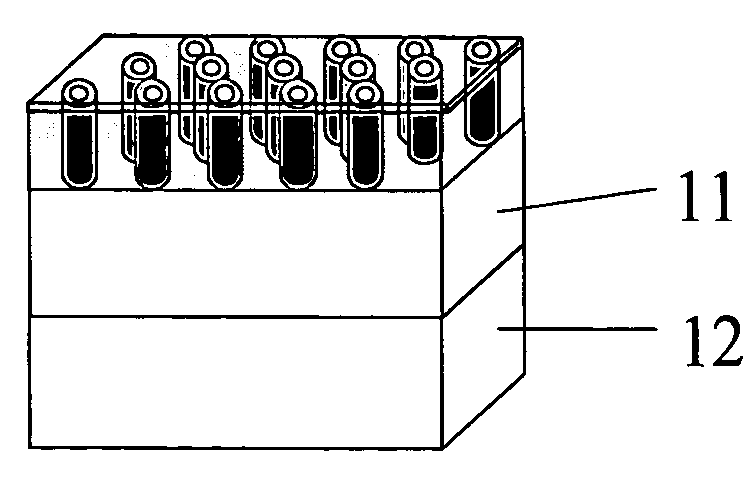
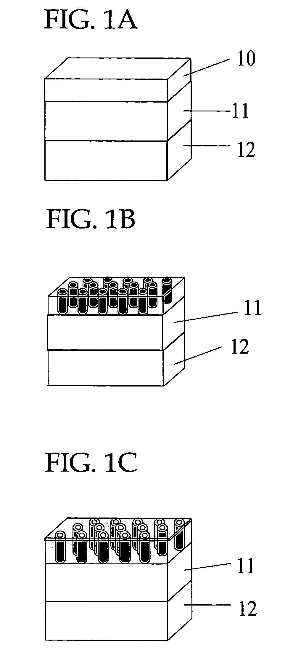
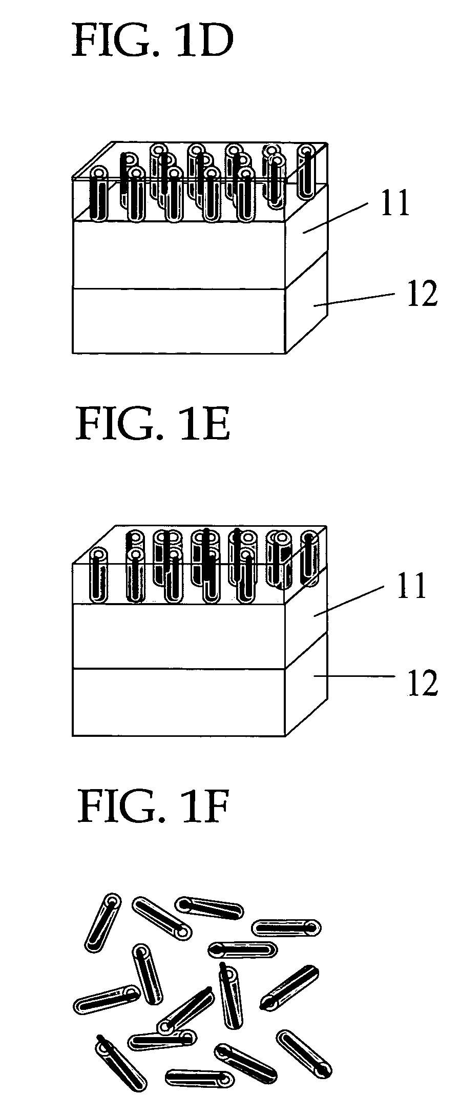
[0098]With reference to FIGS. 1A to 1F, initially, a layer 11 of Nb as the electrode layer 250 nm thick was deposited on a silicon wafer 12 in vacuo by sputtering. Then a layer 10 of aluminum (Al) as the metallic matrix layer was deposited thereon in vacuo by sputtering using an aluminum sputtering target (FIG. 1A). The resulting metallic matrix layer was anodized in a 20% by weight sulfuric acid solution at 20° C. at a voltage of 10 V to thereby form the nanohole structure having a multiplicity of nanoholes (alumina nanoholes, alumina pores) as through-holes extending in a direction substantially perpendicular to the plane of the metallic matrix layer (FIG. 1B). This process is the nanohole structure forming process.

[0099]The metallic matrix layer has a thickness (depth or length of the nanoholes) of 300 nm, and the nanoholes each have an opening with a diameter of 15 nm.

[0100]Next, carbon was allowed to grow on the outer surface of the nanohole structure (alumina nanohole) and the...

example 2

[0109]A series of carbon nanotube composite materials (magnetic materials) were produced by the procedure of Example 1, except that the thickness of the metallic matrix layer was changed to 1000 nm, 500 nm, 300 nm and 50 nm, respectively, and that the plasma treatment was not carried out (FIGS. 2A to 2E). Specifically, a layer 11 of Nb as the electrode layer 250 nm thick was deposited on a silicon wafer 12 in vacuo by sputtering. Then a layer 10 of aluminum (Al) as the metallic matrix layer was deposited thereon in vacuo by sputtering using an aluminum sputtering target (FIG. 2A). The resulting metallic matrix layer was anodized in a 20% by weight sulfuric acid solution at 20° C. at a voltage of 10 V to thereby form the nanohole structure having a multiplicity of nanoholes (alumina nanoholes, alumina pores) as through-holes extending in a direction substantially perpendicular to the plane of the metallic matrix layer (FIG. 2B). Next, carbon was allowed to grow on the outer surface o...

example 3

[0111]Carbon nanotube composite materials (magnetic materials) were produced by the procedure of Example 1, except that the plasma treatment was carried out before the continuous layer coating process (FIGS. 3A to 3E). Specifically, a layer 11 of Nb as the electrode layer 250 nm thick was deposited on a silicon wafer 12 in vacuo by sputtering. Then a layer 10 of aluminum (Al) as the metallic matrix layer was deposited thereon in vacuo by sputtering using an aluminum sputtering target (FIG. 3A). The resulting metallic matrix layer was anodized in a 20% by weight sulfuric acid solution at 20° C. at a voltage of 10 V to thereby form the nanohole structure having a multiplicity of nanoholes (alumina nanoholes, alumina pores) as through-holes extending in a direction substantially perpendicular to the plane of the metallic matrix layer (FIG. 3B). Next, carbon was allowed to grow on the outer surface of the nanohole structure (alumina nanohole) and the inner surfaces of the nanoholes by C...


PUM

PropertyMeasurementUnit
lengthaaaaaaaaaa
depthaaaaaaaaaa
depthaaaaaaaaaa

Abstract

A carbon nanotube composite material contains a carbon nanotube and a continuous layer of a metal covering the inner surface of the carbon nanotube. It is produced by forming a metallic matrix layer and treating the metallic matrix layer to form plural nanoholes in the metallic matrix layer to thereby form a nanohole structure, the nanoholes extending in a direction substantially perpendicular to the plane of the metallic matrix layer; forming carbon nanotubes inside the nanoholes; and covering inner surfaces of the carbon nanotubes with a continuous layer of a metal. It has a well controlled small size, has excellent and uniform physical properties, is resistant to oxidation of the metal with time, is highly chemically stable, has good durability enabling repetitive use, has good coatability, high wettability and dispersibility with other materials, is easily chemically modified, is easily handled and is useful in various fields.

Description

CROSS-REFERENCE TO RELATED APPLICATIONS[0001]This application is based upon and claims the benefits of the priority from the prior Japanese Patent Application No. 2004-145528, filed on May 14, 2004, the entire contents of which are incorporated herein by reference.BACKGROUND OF THE INVENTION[0002]1. Field of the Invention[0003]The present invention relates to a carbon nanotube composite material comprising a carbon nanotube and a metal inside thereof, a magnetic material comprising a carbon nanotube and a magnetic metal inside thereof, and production thereof.[0004]2. Description of the Related Art[0005]Carbon nanotubes (hereinafter may be briefly referred to “CNT”) have been used as novel materials in electronic and electric fields and other fields and have been produced, for example, by arc discharging, laser vaporization, thermal chemical vapor deposition (thermal CVD) or plasma chemical vapor deposition (plasma CVD). Such carbon nanotubes produced by these methods are roughly cla...

Claims


Application Information

Patent Timeline
Patent Type & Authority Patents(United States)
IPC IPC(8): B29D22/00B32B1/08B32B1/00B32B5/16B82B1/00B82B3/00C01B31/02C23C14/32G11B5/706H01F1/00
CPCB82Y10/00B82Y30/00B82Y40/00C01B31/0233G11B5/70605H01F1/0081Y10T428/2991Y10S977/744Y10S977/743Y10T428/2918Y10T428/292Y10T428/268Y10T428/2975Y10T428/13Y10T428/294B82Y25/00C01B32/162
Inventor KYOTANI, TAKASHIOGAWA, TOMONORIITO, KENICHIKIKUCHI, HIDEYUKINAKAO, HIROSHIKUMAI, TSUGIO
Owner FUJITSU LTD
Why Eureka
Try Eureka