Fuel cell separator assembly with diffusion layer, manufacturing method therefor, fuel cell unit, and fuel cell stack

a technology of separators and diffusion layers, which is applied in the direction of cell components, final product manufacturing, sustainable manufacturing/processing, etc., can solve the problems of poor assembling efficiency, difficult to handle the diffusion layer, and too many items being managed, and achieves high performan

Inactive Publication Date: 2008-02-26
HONDA MOTOR CO LTD
View PDF8 Cites 0 Cited by
  • Summary
  • Abstract
  • Description
  • Claims
  • Application Information

AI Technical Summary

Benefits of technology

[0046]According to the above configuration, a fuel cell stack hav

Problems solved by technology

In general, because a diffusion layer has low mechanical strength, it is difficult to handle the diffusion layer.
Moreover, when fuel cell units are assembled, or when a fuel cell stack is assembled while handling the diffusion layers and the separators as independent elements, many elements must be handled, which may lead to poor assembling efficiency, and may lead to too many items being managed, which is troublesome.
In the case in which the diffusion layers and the separators are unified using an adhesive, productivity is inferior because a number of manufacturing processes are required, including a coating process for an adhesive and a curing process for the adhesive, and because, in the curing process, the adhesive must be cured for a several hours at high temperature or at normal temperature.
However, in order to increase the contact pressure, the fuel cell units and the fuel cell stack must have a re

Method used


Image

  • Fuel cell separator assembly with diffusion layer, manufacturing method therefor, fuel cell unit, and fuel cell stack
  • Fuel cell separator assembly with diffusion layer, manufacturing method therefor, fuel cell unit, and fuel cell stack
  • Fuel cell separator assembly with diffusion layer, manufacturing method therefor, fuel cell unit, and fuel cell stack

Examples


first embodiment

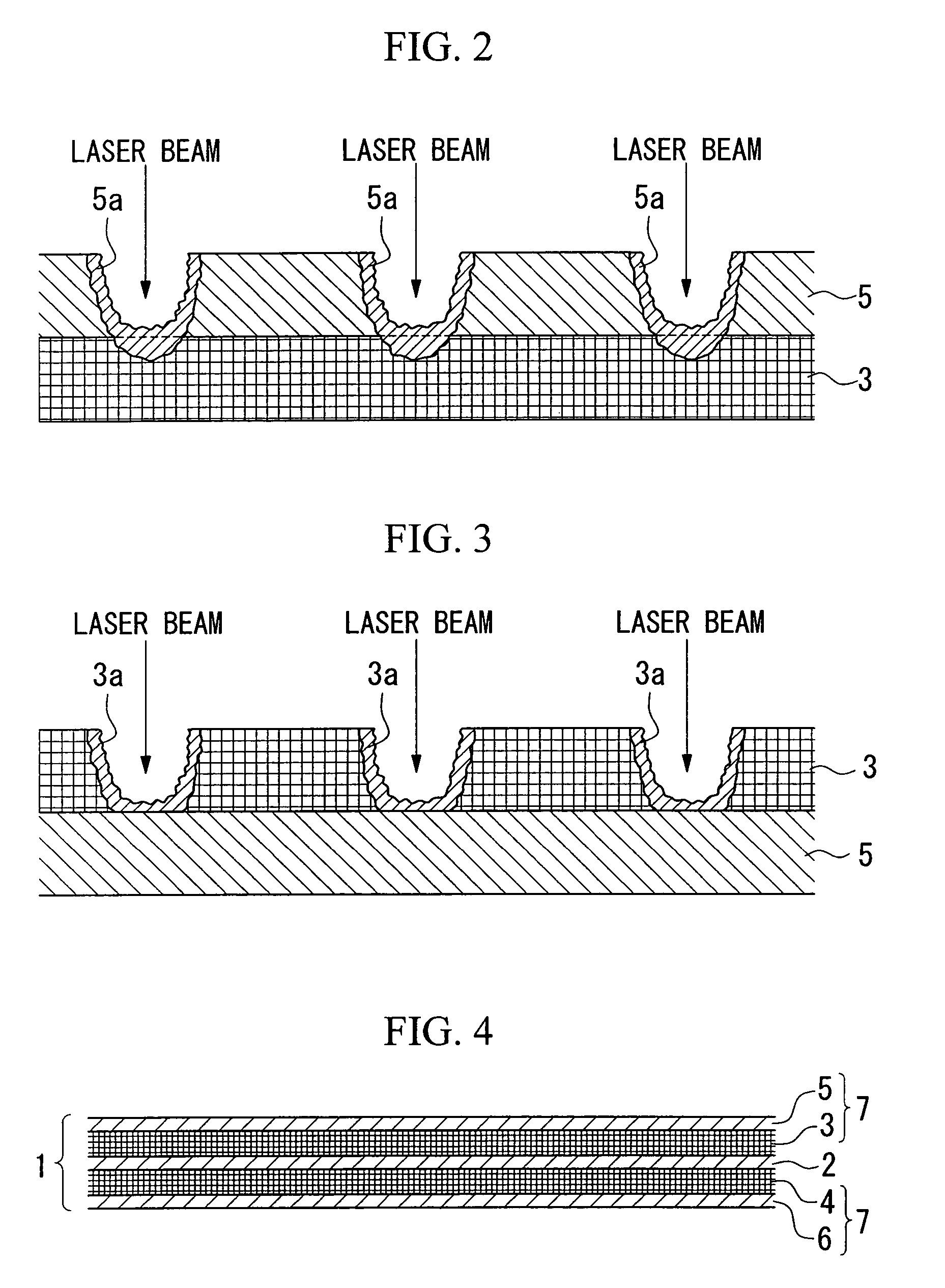
[0069]Through this process, a portion of the melted metal Sa created by locally melting the anode side separator 5 penetrates into the anode side diffusion layer 3 made of a porous metal body. After penetration, the irradiation by the laser beam is terminated, and the anode side separator 5 is allowed to cool naturally so that the melted metal held in the anode side separator 5 and the melted metal penetrated into the anode side diffusion layer 3 are solidified. As a result, the anode side diffusion layer 3 and the anode side separator 5 are connected (i.e., spot-welded) to each other at some portions. The anode side diffusion layer 3 and the anode side separator 5 are unified by making a number of spot-welded portions in the regions where the anode side diffusion layer 3 has surface contact with the anode side separator 5. The spot-welding process is employed in this first embodiment in order to increase productivity; however, the present invention is not limited to this, and a sea...

fourth embodiment

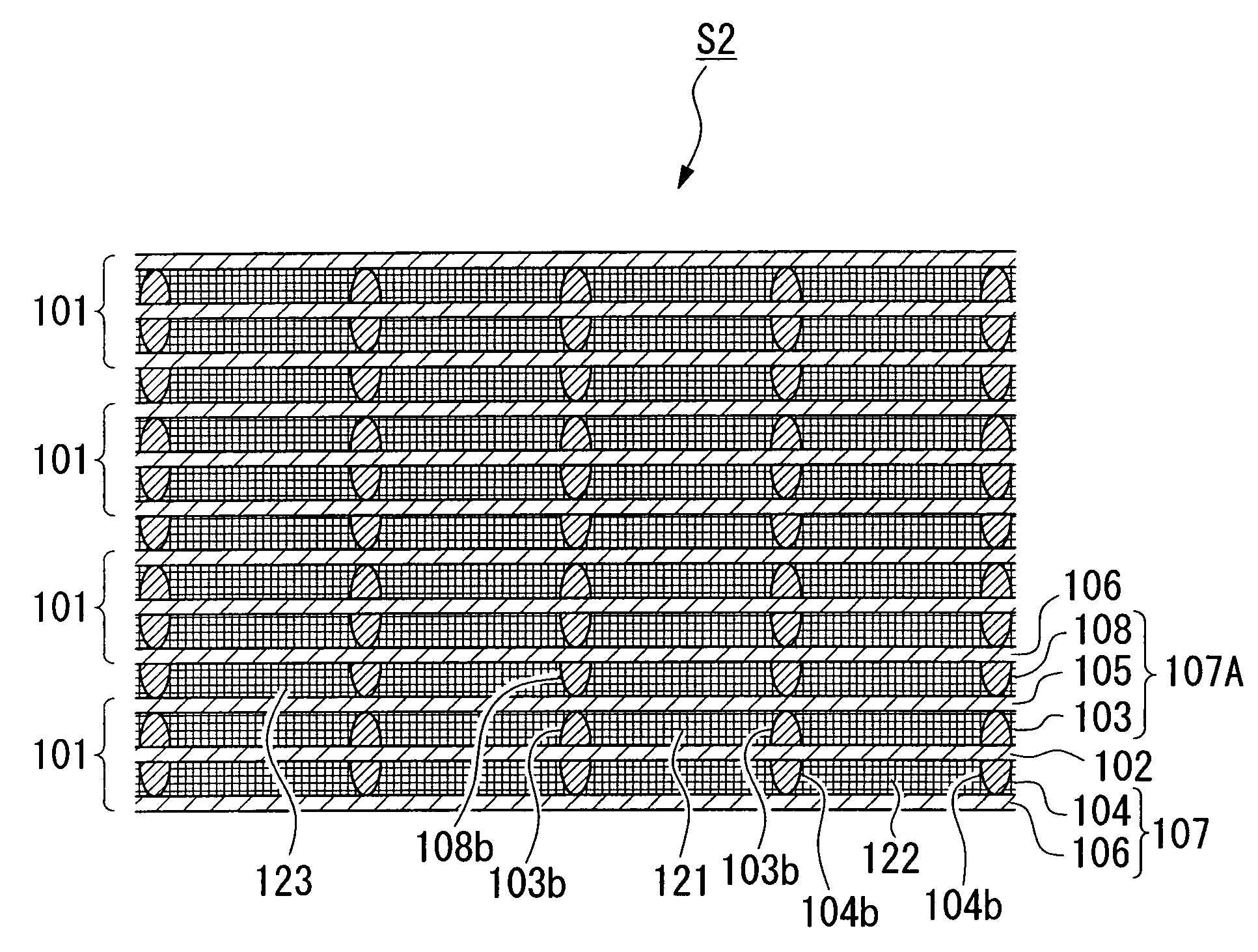
[0082]FIG. 5 is a longitudinal cross-sectional view of a fuel cell stack S1 according to the present invention. The fuel cell stack S1 includes a number of fuel cell units 101 which are stacked with each other.

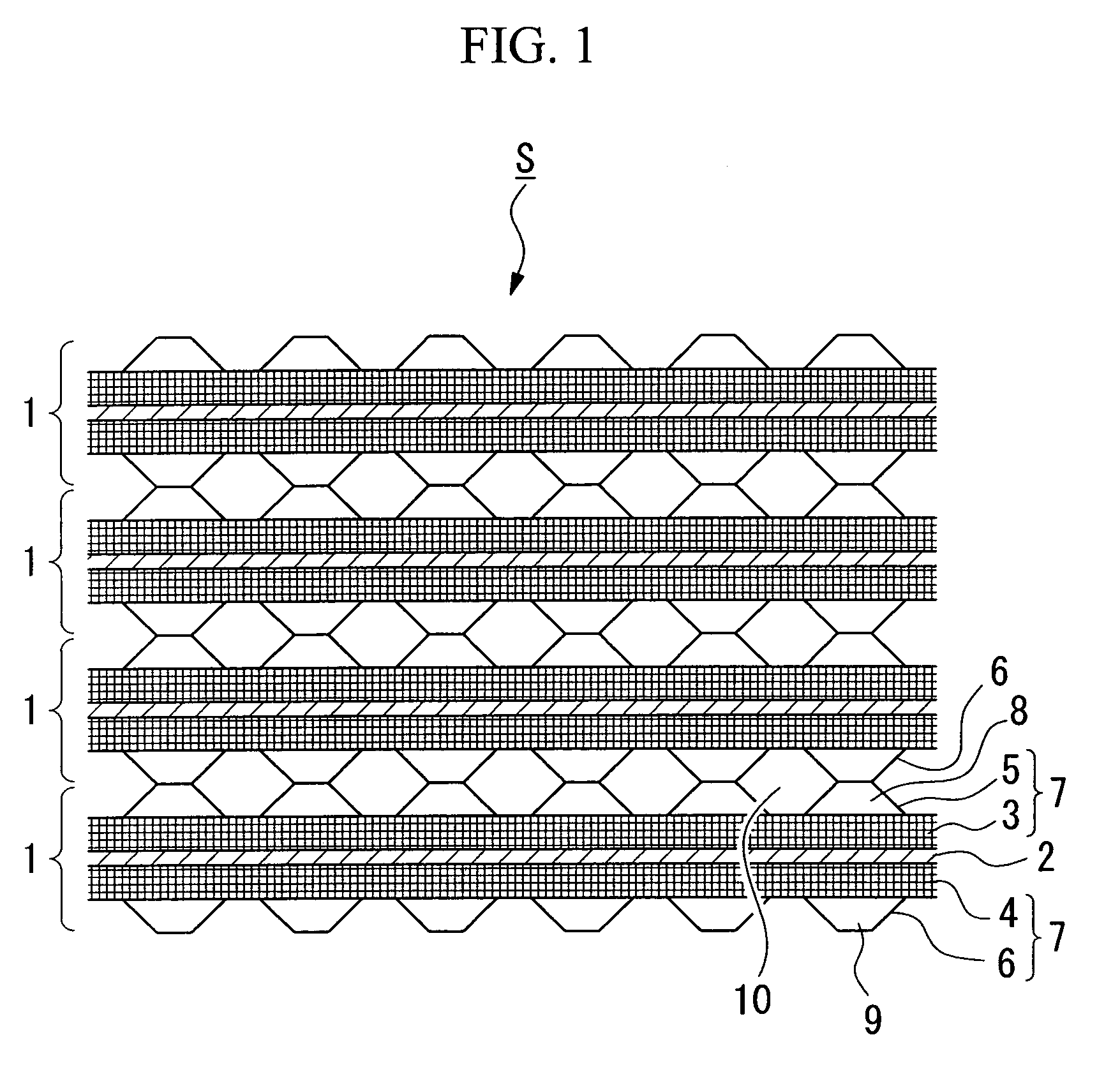
[0083]The fuel cell unit 101 includes a membrane electrode assembly 102 having a solid polymer electrolyte membrane and anode and cathode electrodes that together sandwich the solid polymer electrolyte membrane, an anode side diffusion layer 103 and a cathode side diffusion layer 104 respectively disposed outside of the membrane electrode assembly 102, an anode side separator 105 disposed outside of the anode diffusion layer 103, and a cathode side separator 106 disposed outside of the cathode diffusion layer 104.

[0084]The anode side diffusion layer 103 and the anode side separator 105 have been welded together by laser-welding to form a separator assembly 107 with a diffusion layer, and cathode side diffusion layer 104 and the cathode side separator 106 have been welded toget...

fifth embodiment

[0092]As a fifth embodiment, after laser welding and forming of the flow passage partition 103b, or simultaneously with laser welding and forming of the flow passage partition 103b, the groove 103a may be filled with a padding 103c by making a melted metal flow into the groove 103a, as shown in FIG. 7.

[0093]Whether the flow passage partitions 103b should be formed in a shape having a number of spots, or in a straight shape is determined depending on the desired configuration of the flow passages. For example, as shown in FIG. 8, a number of straight-shaped flow passage partitions 103b, which are parallel to each other, may be made so as to form a fuel flow passage 121 having a zigzag shape (a sixth embodiment). Moreover, as shown in FIG. 9, straight-shaped flow passage partitions 103b may be disposed at random so as to form a fuel flow passage 121 between the flow passage partitions 103b (a seventh embodiment). Furthermore, as shown in FIG. 10, a number of spot-shaped flow passage p...


PUM

PropertyMeasurementUnit
Thicknessaaaaaaaaaa

Abstract

A separator assembly for a fuel cell stack includes a diffusion layer including a porous metal body for diffusing and supplying fuel or oxidizer to an electrode of the fuel cell stack, and a separator including a metal plate which is disposed adjacent to the diffusion layer, and which is provided for separating the fuel and the oxidizer from each other. The diffusion layer and the separator are welded together by laser welding. Flow passage partitions of the metal forming the diffusion layer, which are formed by melting the metal by irradiation by a laser beam and by solidifying the metal, may be formed in the diffusion layer so as to define a flow passage for the fuel or oxidizer in the diffusion layer.

Description

BACKGROUND OF THE INVENTION[0001]1. Field of the Invention[0002]The present invention relates to a fuel cell separator assembly having a metal diffusion layer and a metal separator, relates a manufacturing method therefor, relates to a fuel cell unit including the separator assembly, and relates to a fuel cell stack including the fuel cell units.[0003]Priority is claimed on Japanese Patent Application No. 2002-303043, filed Oct. 17, 2002, and Japanese Patent Application No. 2002-303045, filed Oct. 17, 2002, the contents of which are incorporated herein by reference.[0004]2. Description of Related Art[0005]In the field of fuel cells, a fuel cell unit is known which includes, for example, a solid polymer electrolyte membrane, an anode electrode and a cathode electrode that together sandwich the solid polymer electrolyte membrane, metal diffusion layers respectively disposed outside of the electrodes, and metal separators respectively disposed outside of the metal diffusion layers. In ...

Claims


Application Information

Patent Timeline
IPC IPC(8): H01M2/02B23K9/23B23K15/00B23K26/32B23K26/40H01M8/02
CPCB23K9/232B23K15/0093B23K26/3206B23K26/4005B32B37/065H01M8/0206H01M8/0232H01M8/0254B23K2201/02B32B37/0084B32B2305/026B32B2310/0843B32B2311/00B32B2457/18H01M8/0228H01M8/0267Y02E60/50B23K26/32B23K26/40B23K2101/02B23K2103/50H01M8/0263H01M8/241Y02P70/50H01M8/0258
Inventor NAGOSHI, KENTAROANDOU, KEISUKEMATSUBARA, TAKESHI
Owner HONDA MOTOR CO LTD
Why Eureka
Try Eureka