Dielectric reproducing apparatus, dielectric recording apparatus, and dielectric recording/reproducing apparatus

a dielectric recording and reproducing technology, applied in the field of dielectric reproducing apparatus, dielectric recording apparatus and dielectric recording/reproducing apparatus, can solve the problems of difficult to overcome the limit, the pickup is relatively large, and the recording density is limited to 1 t bit/inch

Inactive Publication Date: 2008-02-26
CHO YASUO +1
View PDF81 Cites 17 Cited by
  • Summary
  • Abstract
  • Description
  • Claims
  • Application Information

AI Technical Summary

Benefits of technology

[0009]It is therefore an object of the present invention to provide a dielectric reproducing apparatus, a dielectric recording apparatus, and a dielectric recording / reproducing apparatus for recording / reproducing data in / from a dielectric recording medium by using the SNDM, which can perform high-speed recording / reproducing and which are provided with a small, integration-capable recording / reproducing head.

Problems solved by technology

However, the pickup is relatively large, which is not appropriate for high-speed reading, and the size of the recording pit is defined by the diffraction limit of light, so that its recording density is limited to 50 G bit / inch2.
However, the recording density is limited to 1 T bit / inch2 because of thermal fluctuation of magnetic recording information and the presence of a Bloch wall in a portion in which a code is reversed.
Even if patterned media are used considering the above cause, it is difficult to overcome this limit.
The coherent detection is suitable for high accurate detection, to be sure, but it takes time to obtain a detection result.
Further, a device or circuit for coherent detection (e.g. a lock-in amplifier) is large in size.

Method used


Image

  • Dielectric reproducing apparatus, dielectric recording apparatus, and dielectric recording/reproducing apparatus
  • Dielectric reproducing apparatus, dielectric recording apparatus, and dielectric recording/reproducing apparatus
  • Dielectric reproducing apparatus, dielectric recording apparatus, and dielectric recording/reproducing apparatus

Examples


first embodiment

(First Embodiment of Dielectric Recording / Reproducing Apparatus)

[0078]A first embodiment of the dielectric recording / reproducing apparatus associated with the present invention will be explained with reference to FIG. 8.

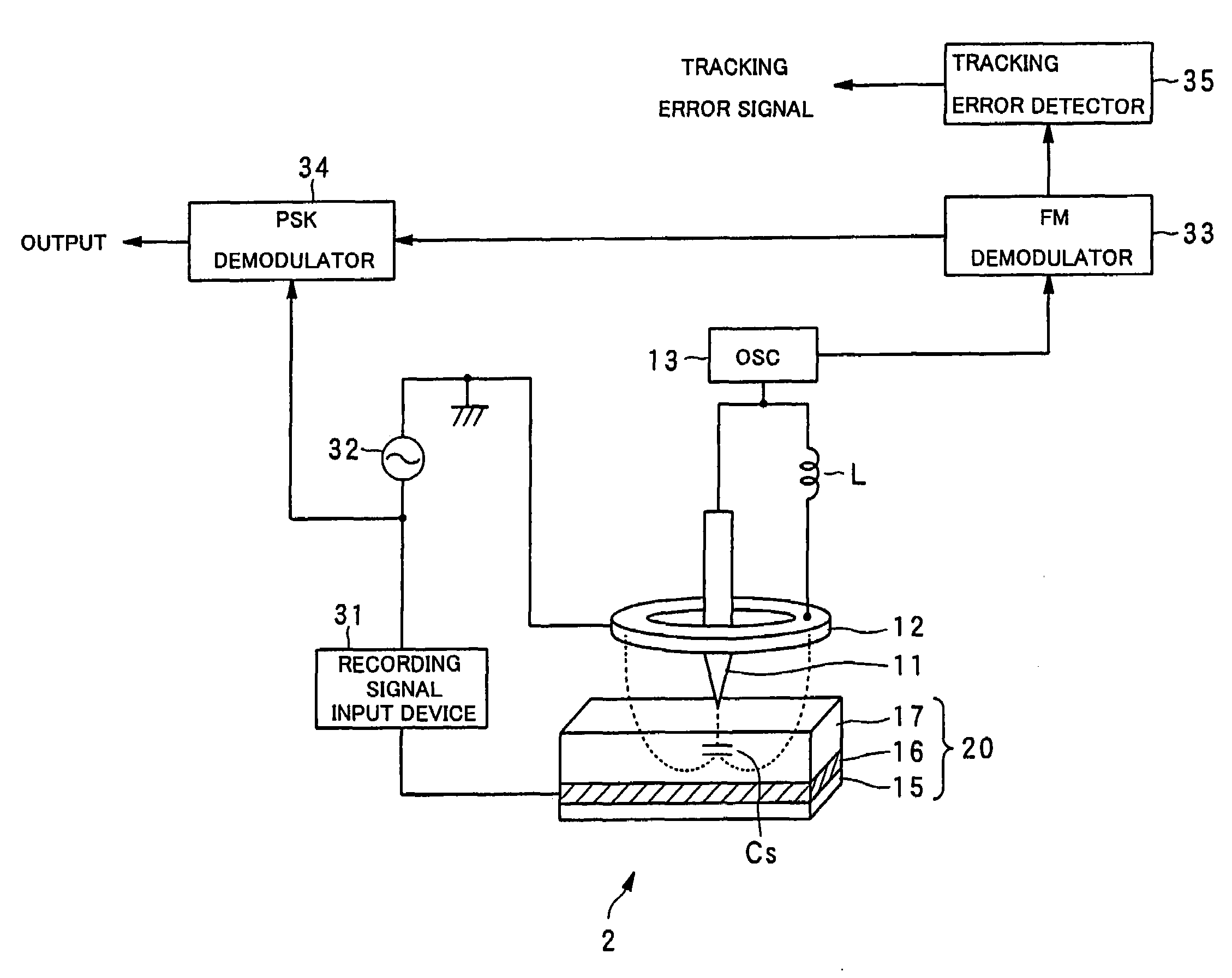
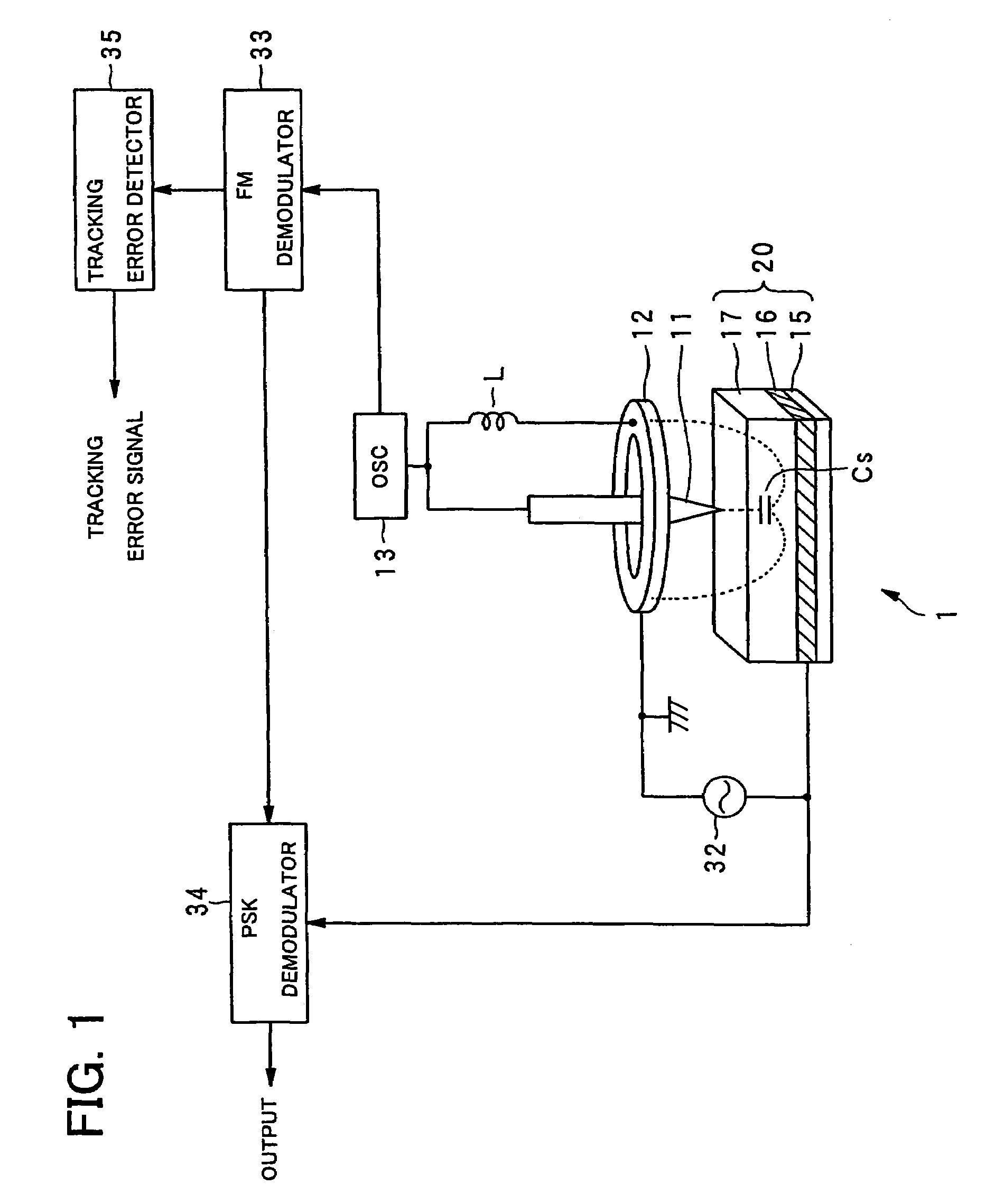
[0079]A dielectric recording / reproducing apparatus 3 is provided with: the probe 11 for applying an electric field with its tip portion facing to the ferroelectric material 17 of the ferroelectric recording medium 20; the return electrode 12 for returning the electric field applied from the probe 11; the inductor L placed between the probe 11 and the return electrode 12; the oscillator 13 which oscillates at a resonance frequency determined from the inductor L and the capacitance Cs in a portion formed in the ferroelectric material 17 just under the probe 11 and polarized correspondingly to recorded information; a switch 30 for switching circuit connections depending on whether the data recording is performed or the data reproducing is performed; the recording signal...

second embodiment

(Second Embodiment of Dielectric Recording / Reproducing Apparatus)

[0083]A second embodiment of the dielectric recording / reproducing apparatus associated with the present invention will be explained with reference to FIG. 9.

[0084]A dielectric recording / reproducing apparatus 4 is provided with: the probe 11 for applying an electric field with its tip portion facing to the ferroelectric material 17 of the ferroelectric recording medium 20; the return electrode 12 for returning the electric field applied from the probe 11; the inductor L placed between the probe 11 and the return electrode 12; the oscillator 13 which oscillates at a resonance frequency determined from the inductor L and the capacitance Cs in a portion formed in the ferroelectric material 17 just under the probe 11 and polarized correspondingly to recorded information; the switch 30 for switching circuit connections depending on whether the data recording is preformed or the data reproduction is performed; the recording s...

third embodiment

(Third Embodiment of Dielectric Recording / Reproducing Apparatus)

[0088]A third embodiment of the dielectric recording / reproducing apparatus associated with the present invention will be explained with reference to FIG. 10. The third embodiment indicates an example in the case where the inductance of the inductor L has a large effect on the frequency component of a recording signal.

[0089]A dielectric recording / reproducing apparatus 5 is provided with: the probe 11 for applying an electric field with its tip portion facing to the ferroelectric material 17 of the ferroelectric recording medium 20; the return electrode 12 for returning the electric field applied from the probe 11; the inductor L placed between the probe 11 and the return electrode 12; the oscillator 13 which oscillates at a resonance frequency determined from the inductor L and the capacitance Cs in a portion formed in the ferroelectric material 17 just under the probe 11 and polarized correspondingly to recorded informa...


PUM

PropertyMeasurementUnit
frequencyaaaaaaaaaa
frequencyaaaaaaaaaa
frequencyaaaaaaaaaa

Abstract

A dielectric reproducing apparatus is provided with: a probe for applying an electric field to a dielectric material of a dielectric recording medium; a return electrode for returning the electric field applied from the probe; an inductor placed between the probe and the return electrode; an oscillator which oscillates at a resonance frequency determined from the inductor and a capacitance formed in the dielectric material just under the probe; an alternating current (AC) signal generation device for generating an AC signal which is applied to the probe; a frequency modulation (FM) demodulator for demodulating a FM modulation signal modulated by the capacitance corresponding to the polarization state owned by the dielectric material just under the probe; and a phase-shift keying (PSK) demodulator for reproducing data from the demodulated signal.

Description

BACKGROUND OF THE INVENTION[0001]1. Field of the Invention[0002]The present invention relates to a dielectric reproducing apparatus, a dielectric recording apparatus and a dielectric recording / reproducing apparatus for recording / reproducing information with high density in / from microdomains in a dielectric substance.[0003]2. Description of the Related Art[0004]As high-density, large-capacity recording / reproducing apparatuses of randomly accessible type, there are known an optical disc apparatus and a hard disc drive (HDD) apparatus. Moreover, a recording / reproducing technique using a scanning nonlinear dielectric microscopy (SNDM) for the nanoscale analysis of a dielectric (ferroelectric) material has been recently proposed by the inventors of the present invention.[0005]In optical recording, which uses an optical pickup with a laser as a light source, data is recorded by forming pits that are concave-convex on a disc surface or forming a crystal phase or amorphous phase of a phase ...

Claims


Application Information

Patent Timeline
Patent Type & Authority Patents(United States)
IPC IPC(8): G11B7/00G11B20/14G11B9/00G11B9/02G11B9/06G11B9/14G11B11/08
CPCB82Y10/00G11B9/02G11B9/06G11B9/14G11B11/08
Inventor CHO, YASUOONOE, ATSUSHI
Owner CHO YASUO
Why Eureka
Try Eureka