Plasma torch with corrosive protected collimator

a collimator and corrosive protection technology, applied in plasma welding apparatus, plasma welding apparatus, manufacturing tools, etc., can solve the problem of rapidly corroding copper surfaces exposed to acidic conditions

Active Publication Date: 2008-03-11
PHOENIX SOLUTIONS CO
View PDF18 Cites 5 Cited by
  • Summary
  • Abstract
  • Description
  • Claims
  • Application Information

AI Technical Summary

Problems solved by technology

The chlorine can combine with hydrogen to form hydrochloric acid, which can rather rapidly corrode copper surfaces exposed to the acid.
This necessitates frequent shut-down and replacement of the collimators before corrosion reaches the point where the leaking can occur.

Method used


Image

  • Plasma torch with corrosive protected collimator
  • Plasma torch with corrosive protected collimator
  • Plasma torch with corrosive protected collimator

Examples


Embodiment Construction

[0029]Certain terminology will be used in the following description for convenience in reference only and will not be limiting. The words “upwardly”, “downwardly”, “rightwardly” and “leftwardly” will refer to directions in the drawings to which reference is made. The words “inwardly” and “outwardly” will refer to directions toward and away from, respectively, the geometric center of the device and associated parts thereof. Said terminology will include the words above specifically mentioned, derivatives thereof and words of similar import.

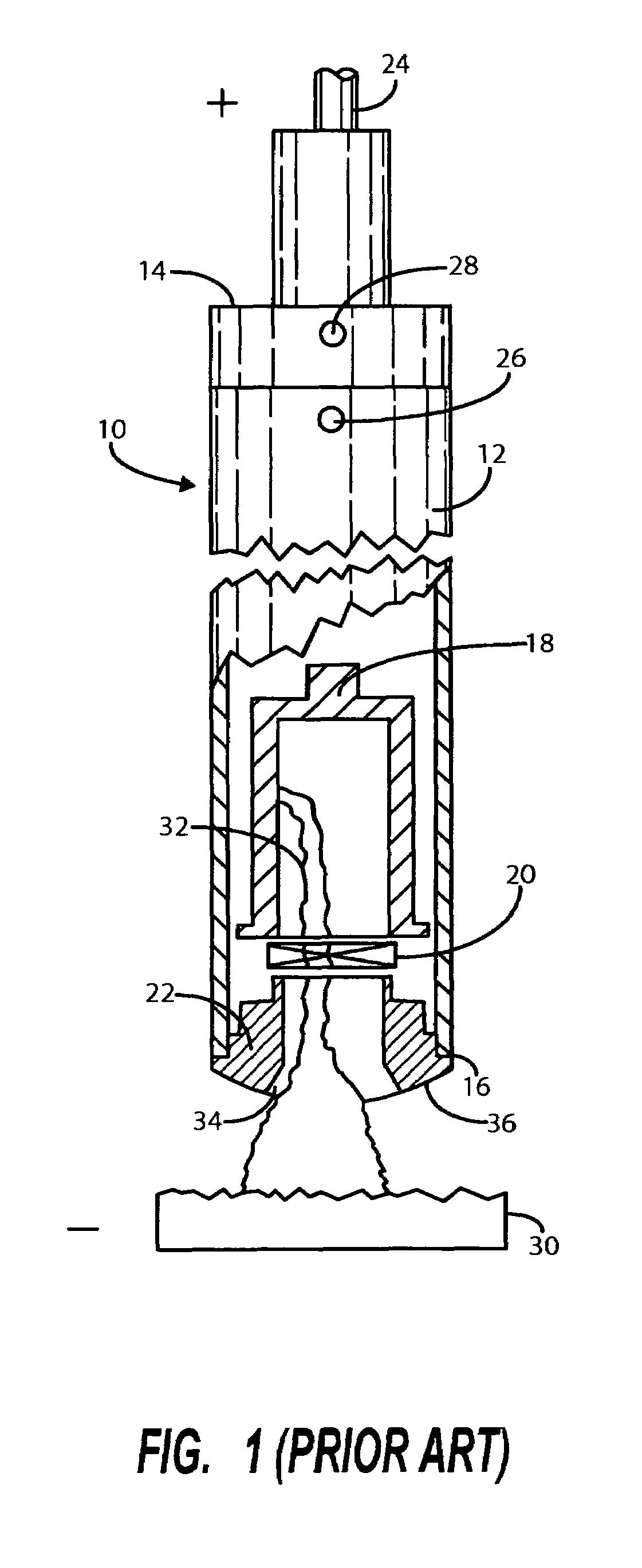
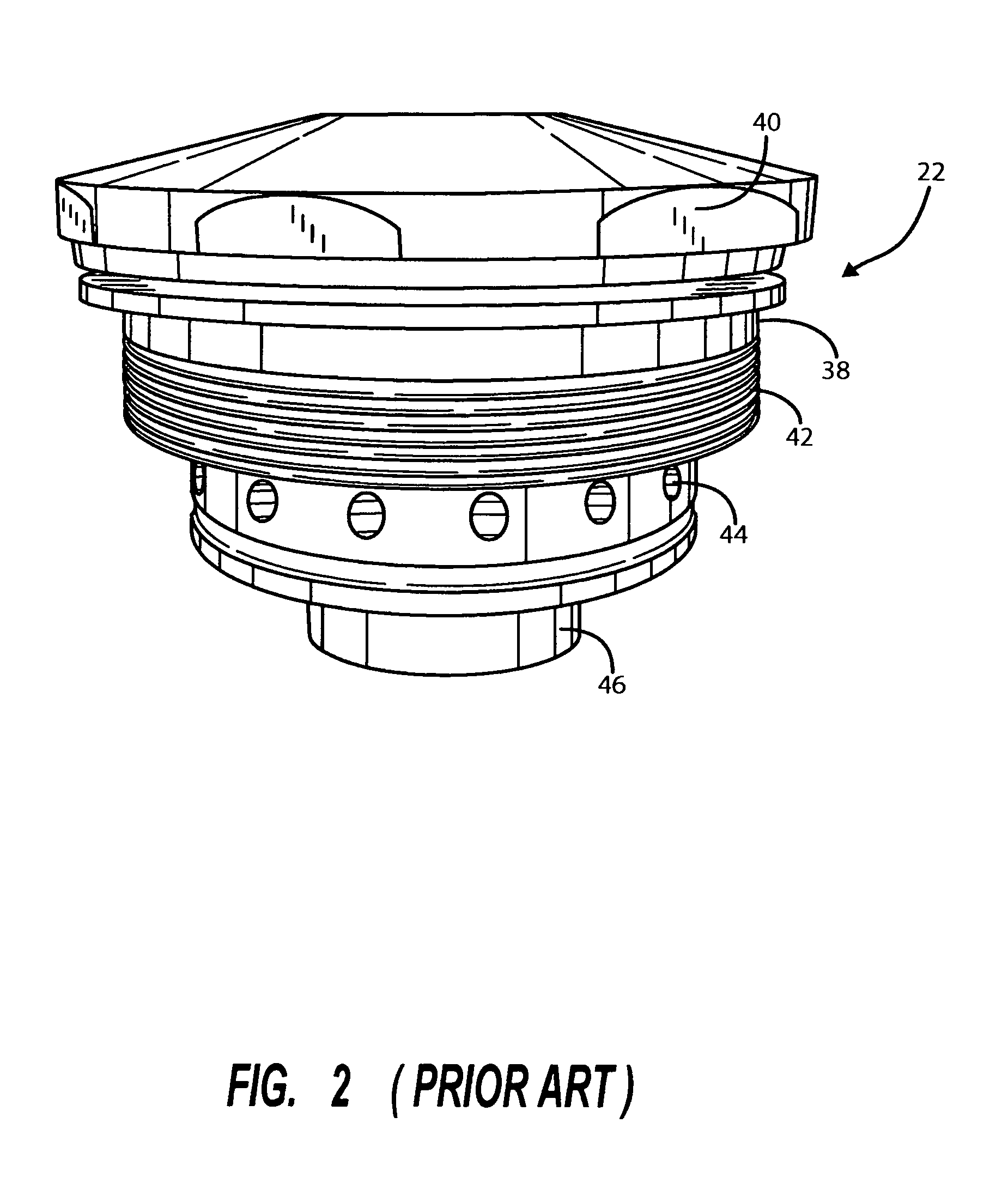
[0030]Referring first to FIG. 1, there is shown a conventional, prior art plasma torch. It is indicated generally by numeral 10. It is seen to include an outer steel shroud 12 having a proximal end 14 and a distal end 16. The shroud surrounds various internal components of the torch, including a rear electrode 18, a gas vortex generator 20, as well as other tubular structures creating cooling water passages leading to a collimator member 22 that is...


PUM

PropertyMeasurementUnit
temperatureaaaaaaaaaa
thicknessaaaaaaaaaa

Abstract

To protect the collimator of a transferred plasma arc torch from premature failure due to corrosion, an anti-corrosive covering is applied on the exposed face surface and a portion of the inner exit bore of the collimator. The specification describes several methods for producing the collimator for a plasma torch having an anti-corrosive coating or cladding on the exposed surfaces thereof, including electroplating, electroless plating, flame spraying, plasma spraying, plasma transferred arc, hot isostatic pressing and explosive cladding.

Description

BACKGROUND OF THE INVENTION[0001]I. Field of the Invention[0002]This invention relates generally to the field of plasma arc torches, and more particularly to methods and apparatus for treating the collimator employed in the plasma arc torch to reduce the effects of corrosion and thereby extend the service life of the collimator.[0003]II. Discussion of the Prior Art[0004]Plasma arc torches, as known in the prior art, are capable of efficiently converting electrical energy to heat energy producing extremely high temperatures. For example, a plasma arc torch may typically operate in a range as high as from 6000° C. to 7000° C.[0005]Plasma arc torches are known which use water-cooled, reverse polarity, hollow copper electrodes. A gas, such as argon, nitrogen, helium, hydrogen, air, methane or oxygen, is injected through the hollow electrode, ionized and rendered plasma by an electric arc and injected into or integrated with a heating chamber or process.[0006]As is explained in the Hanus...

Claims


Application Information

Patent Timeline
Patent Type & Authority Patents(United States)
IPC IPC(8): B23K10/00
CPCH05H1/34H05H1/48H05H2001/3421H05H2001/3457H05H2001/3484H05H1/3421H05H1/3457H05H1/3484
Inventor HANUS, GARY J.REEVE, RODNEY E.STAHL, TODD J.
Owner PHOENIX SOLUTIONS CO
Why Eureka
Try Eureka